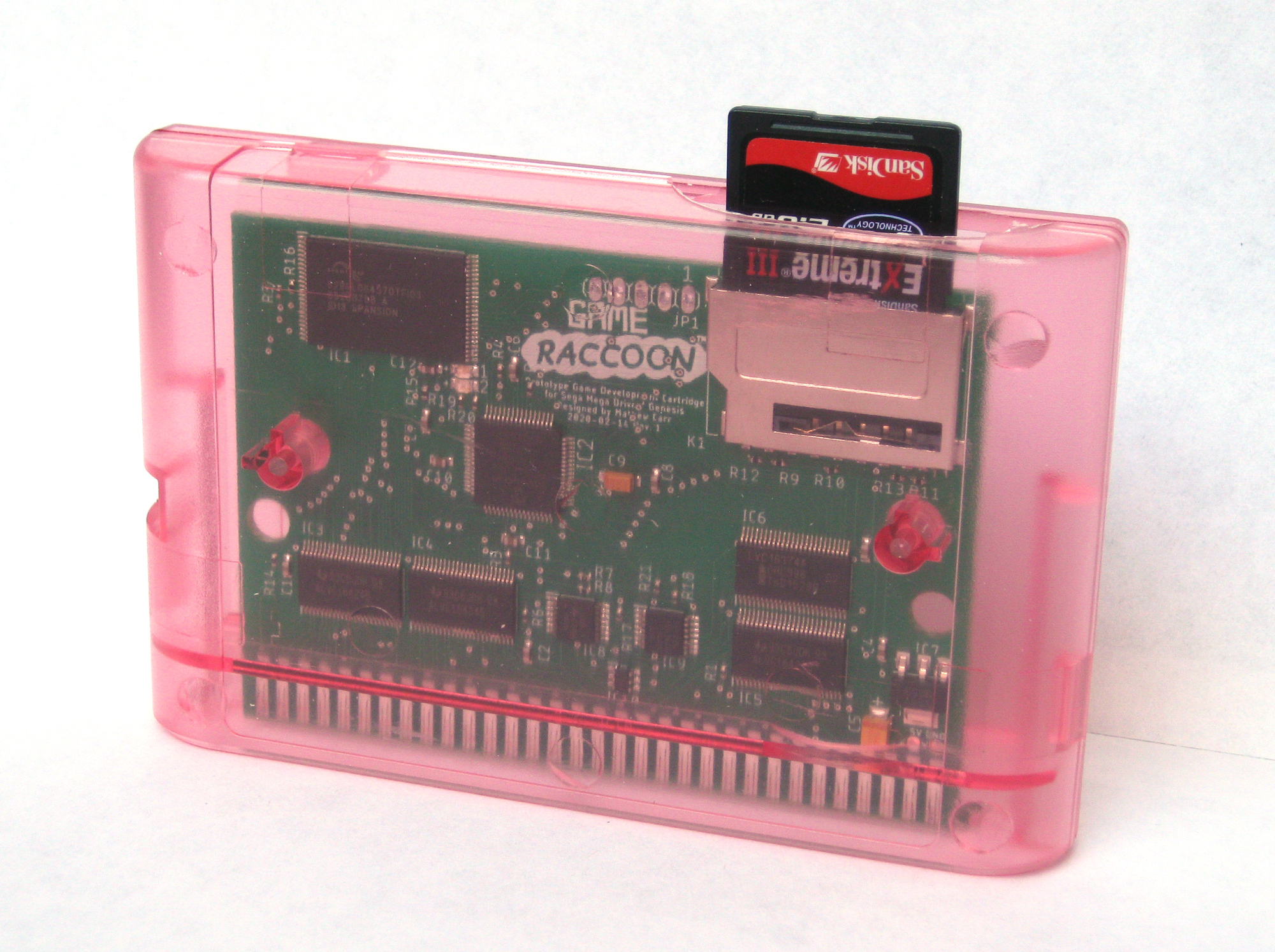
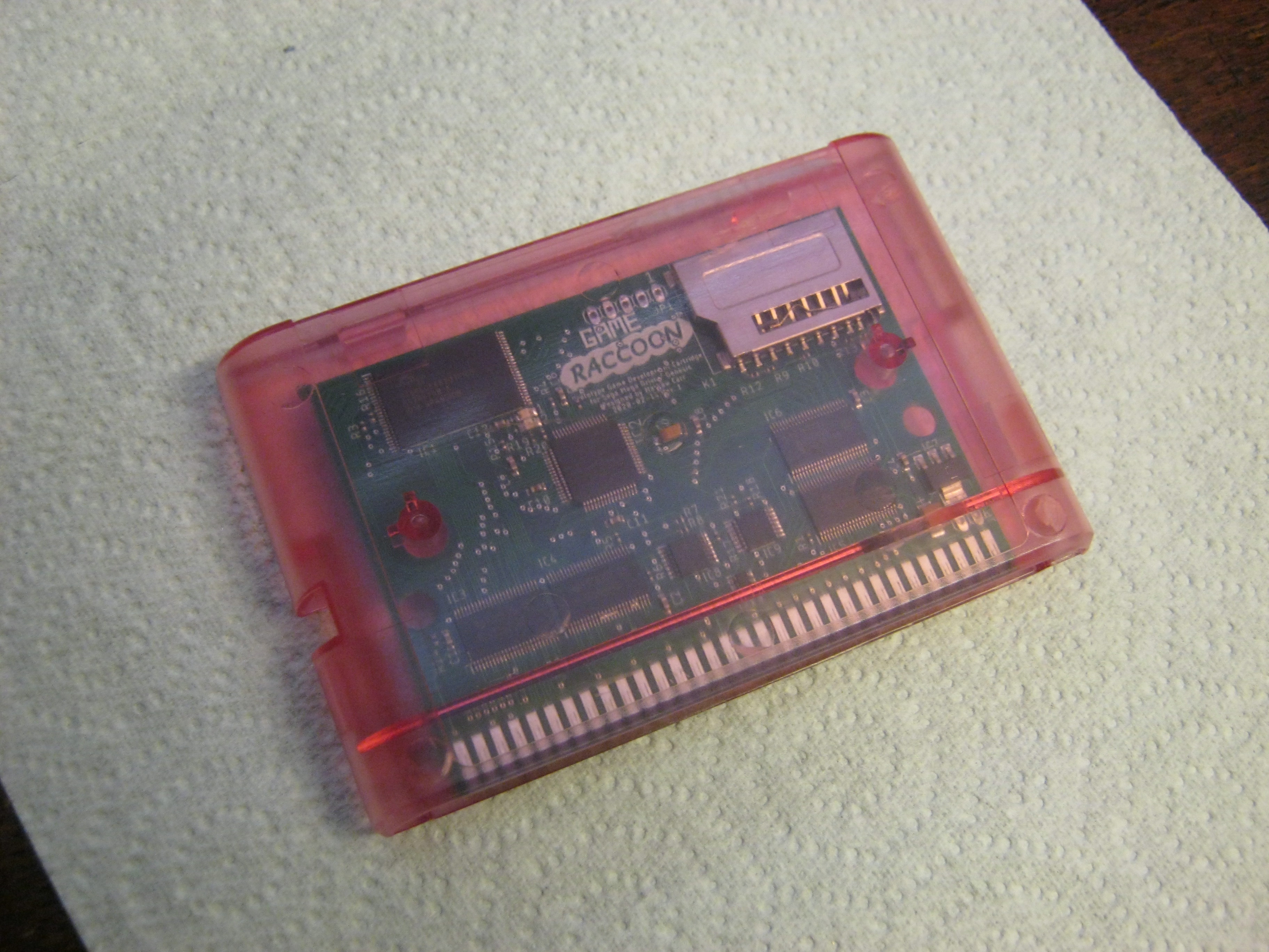
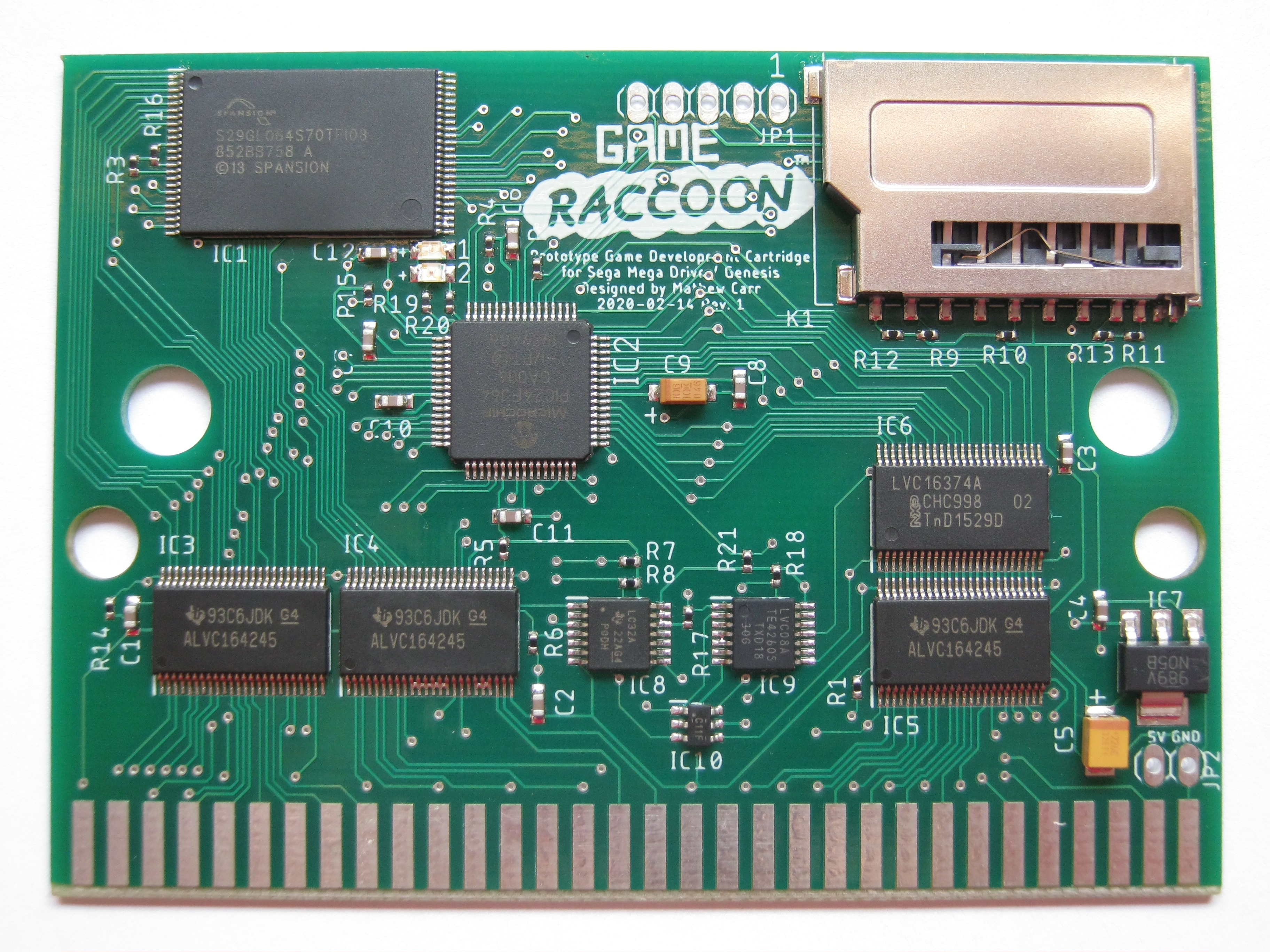
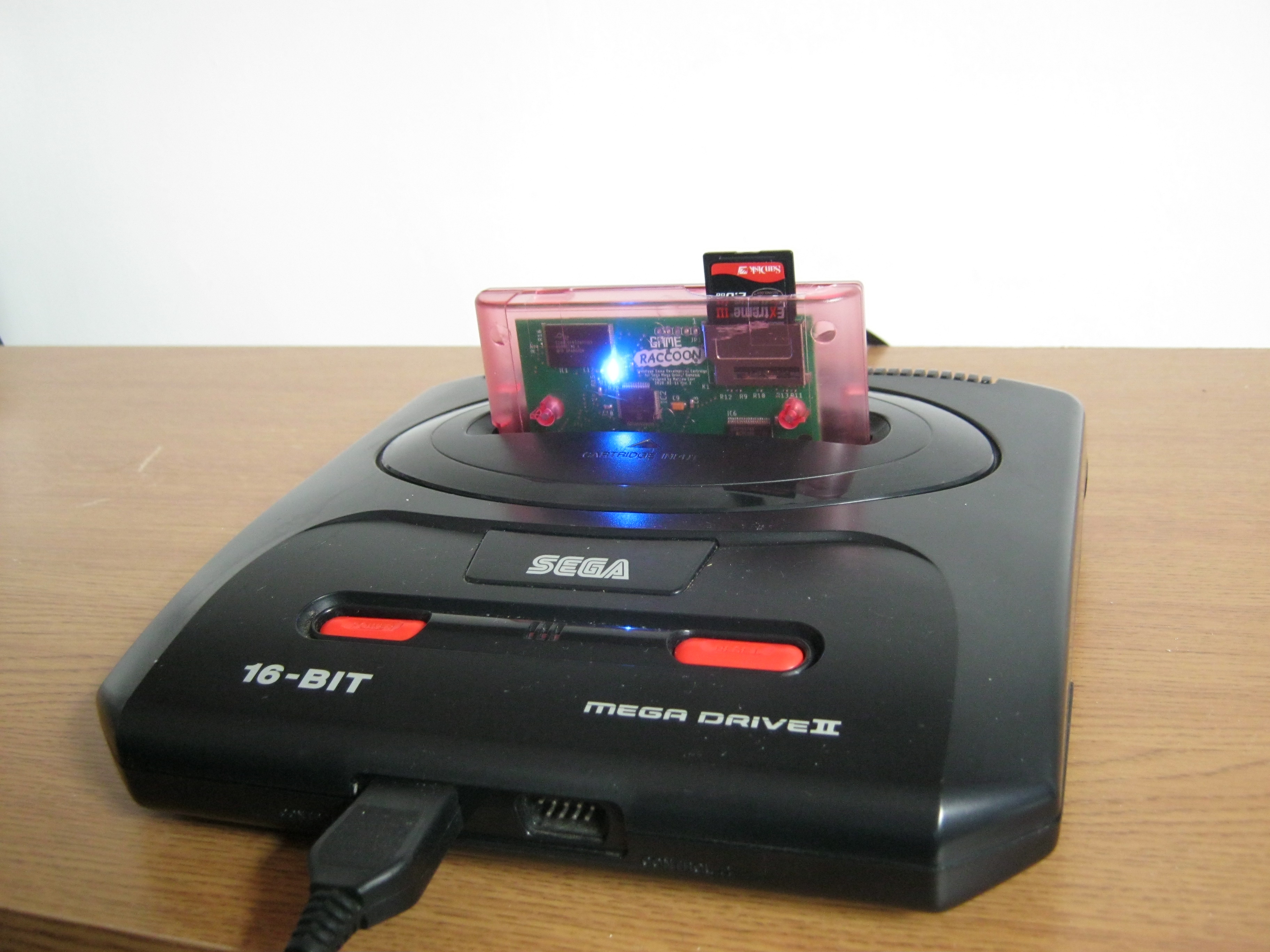
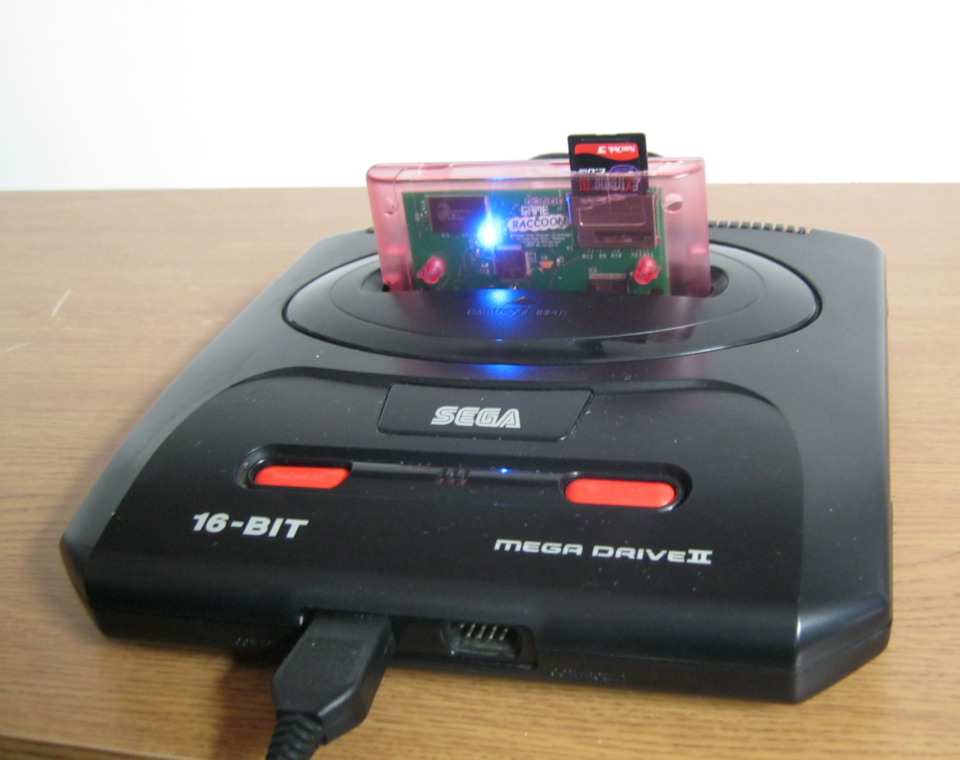
Back to Game Raccoon index...

Game Raccoon Hardware Revision 1 Technical Report - July 2020

Game Raccoon Hardware Revision 1 dated 2020-07-07, firmware 2020-07-07 The Game Raccoon project is a project for me to practice my hardware design and software skills. The product of this work is a new cartridge for the Sega Mega Drive which allows software developers a straightforward, easy-to-use method to prototype new games on Sega Mega Drive, Genesis or Nomad hardware without any hardware knowledge or the use of tools such as EEPROM rewriters. This page is a brief overview of the Game Raccoon Hardware Revision 1 cartridge, and what it can and cannot do. For a more narrative progression, please see the post 'Matt's Chronoblogical Misadventures in Game Raccoon Land Revision 1 - July 2020'.

What is the Game Raccoon?

The Game Raccoon Revision 1 is a cartridge for the Sega Mega Drive which allows software developers to boot game images stored on SD card on Mega Drive hardware. An internal menu allows the user to select an image to be written to the internal memory, which can then be played as if it were running from a Mask ROM cartridge. The Game Raccoon is entirely self-contained and requires no electronics knowledge to use. Main features: • 4 Megabyte independent menu and game partitions on on-board 16-bit Flash memory. • 5V compliant with full use of level-shifting transceivers. • SD card support supporting FAT filesystems. • Reprogrammable PIC microcontroller handles SD card communication and Flash programming.

What software can I use on my Game Raccoon?

There are many homebrew Sega Mega Drive games and demos available for download on itch.io, including: TanglewoodL'abbaye des MortsFoxyLandOld TowersMisplacedYazzieGLUFDevwill TooGenesis Metal Fury IrenaGriel's Quest: Quest for the Holy Porrón All these games have been tried on the Game Raccoon Revision 1 on a PAL Model 1 Sega Mega Drive with TMSS. The above images are photos taken from a TV screen, just how they'd have done it back in the day for magazines or box layouts. :) Many of the above titles were programmed with SGDK, which provides a way to make your own Mega Drive games and works great with the Game Raccoon as you can see! N.B. This project is not endorsed by, supported by or associated with the developers or publishers of any of the above games, or of SGDK. In addition, over fifty homebrew Sega Mega Drive games are listed on Sega Retro, with many of them being offered as free downloads. More new games for the Mega Drive / Genesis are being released every month, these are tracked on release sites such as pdroms.de. My own YM2612 Instrument Editor with graphics by Aly James allows you to explore the sounds the Mega Drive's YM2612 sound chip is capable of producing. There are many demo productions - that is, free running animations showing novel video and audio effects - available for download on Pouet, such as: Overdrive by TiTAN. • Stuck Somewhere in Time by Up Rough, Insane & Titan. • Red Eyes by Kabuto, Exocet and Remute. • Bad Apple by FLM. • The Art of LeonBli by Resistance. The retail games Zero Tolerance by Technopop (as well as a prototype of the sequel), and Wiz 'n' Liz: The Frantic Wabbit Rescue are offered free to download from their original authors. No games are hosted on the Game Raccoon website.

Board design and components

Components: • A non-volatile 
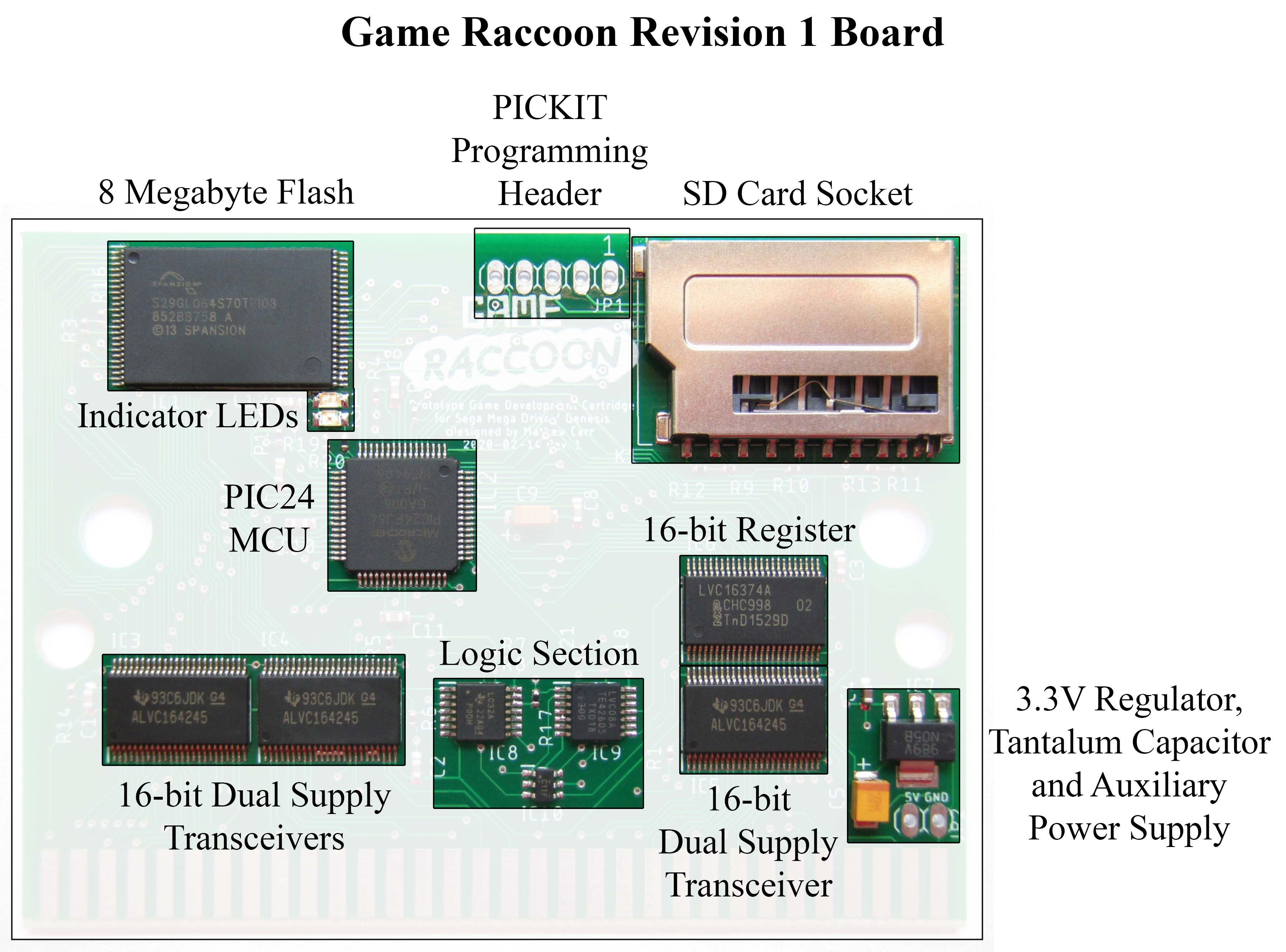
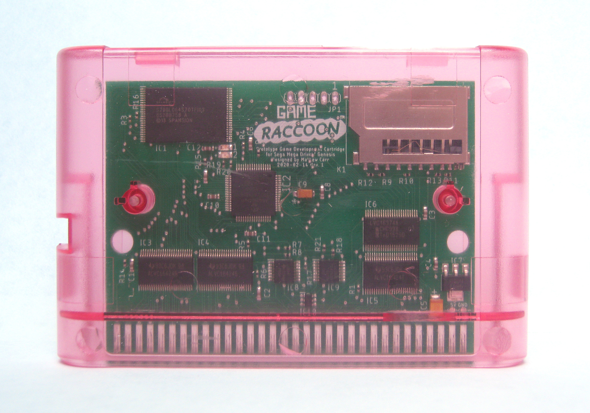
8 Megabyte Flash memory module provides space for both the boot-up menu, and a 4 Megabyte partition for game images. The boot menu can be updated.
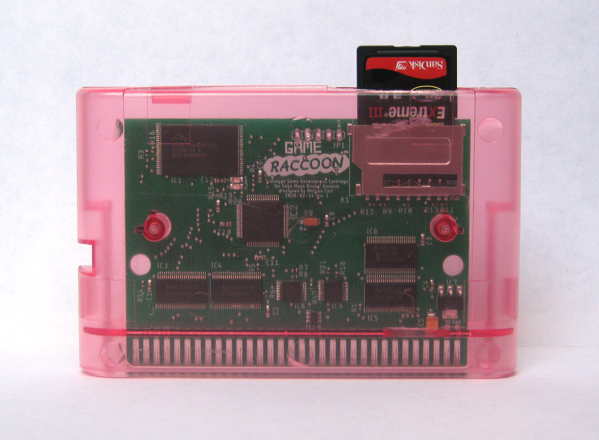
 • A standard size SD card socket allows the use of SD cards (tested up to 2 GB, may work with larger!). • A PIC24 MCU handles communication with the SD card, Flash module and cartridge state logic. • A hardwired Logic Section provides rapid signal decoding for high software compatibility mimicking a Mask ROM cartridge. • Three level-shifting transceivers interface the 5V Mega Drive chipset to the high-speed, low-power internal 3.3V Game Raccoon components. • A register enables bidirectional communication between the Mega Drive and PIC processor to control the Game Raccoon hardware from the Mega Drive, allowing the user to select game images to be reprogrammed from the Mega Drive itself. • A 5-pin PICKIT header allows the PIC MCU to be reprogrammed by enthusiasts.
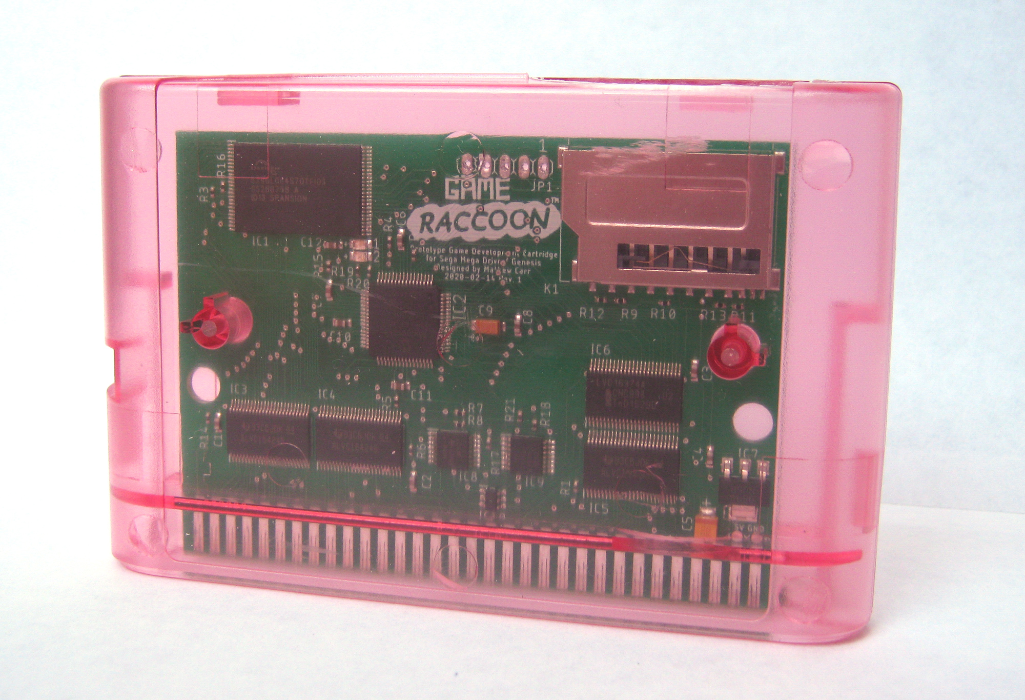
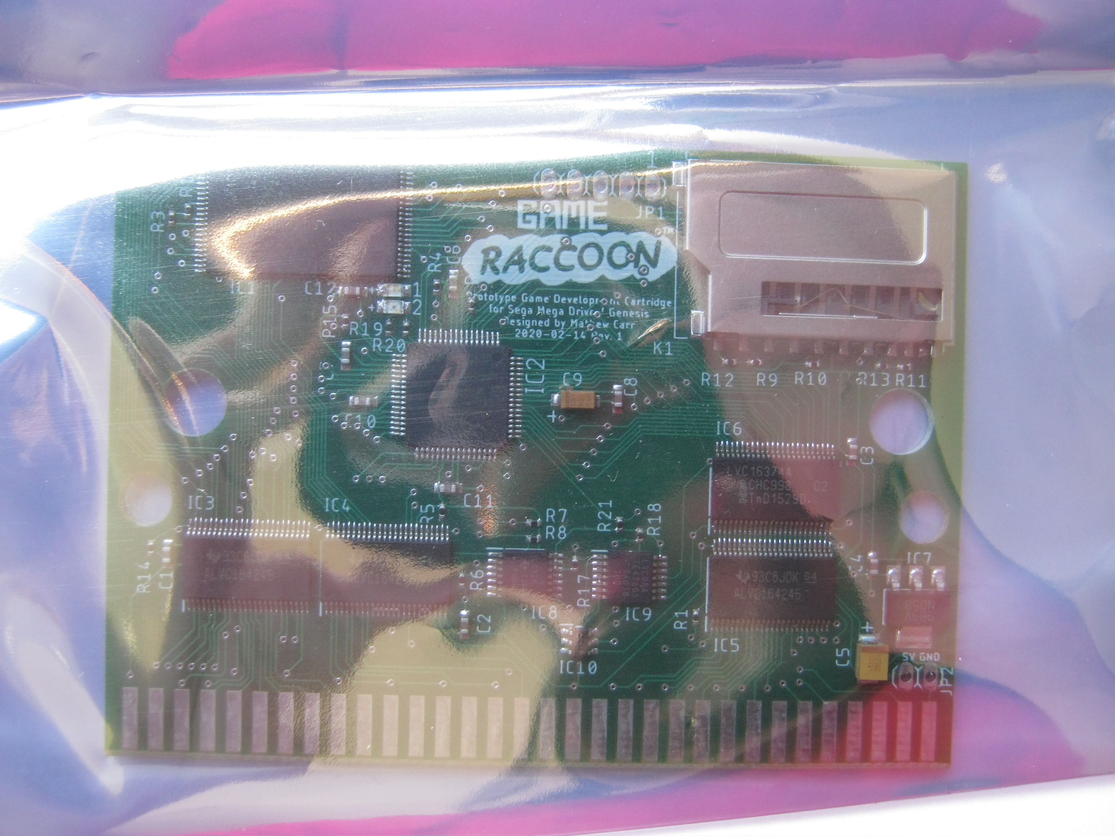
 Transceivers: 
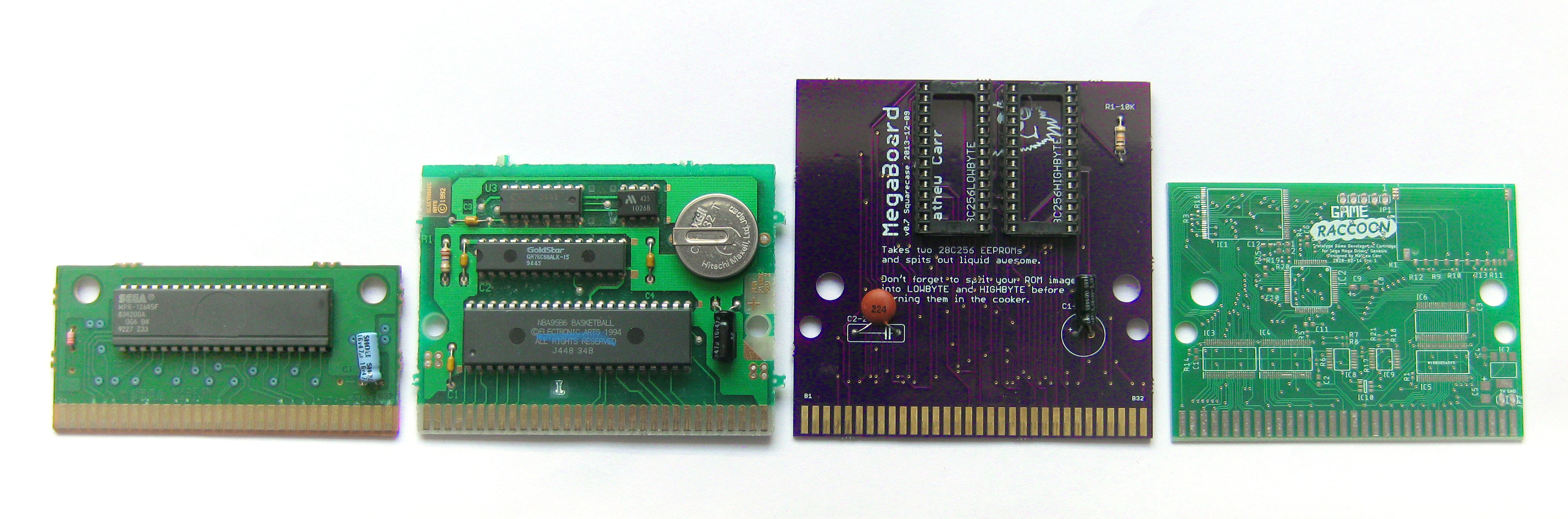
There are three 16-bit dual supply transceivers at the lower edge of the board. The leftmost two are collectively the 'Address/Signals Bus' transceivers, and the rightmost transceiver is the 'Data Bus' transceiver. The dual supply transceivers perform the function of translating between the Game Raccoon's internal 3.3V signalling and the 5V signalling expected by the Mega Drive. No 5V signal from the Mega Drive is connected to any other component on the board in any way, with the exception of a pull-up on D0 described below. (I've been told that the Mega Drive is compatible with a 3.3V high logic level - the 68000 processor datasheet claims a VIH minumum of 2.0V - and several (unofficial) Mega Drive devices communicate in this way, but I didn't want to chance it. I didn't have any information about the custom chips on the motherboard, and their capacitances, etc.) The dual supply transceivers use both the 5V and internal 3.3V supplies. The dual supply transceivers are also used to control the directionality and tri-statedness of the communicaton between the Game Raccoon PCB and the Mega Drive's buses. The directionality of the Address/Signals Bus transceivers are set to 5V -> 3.3V. The Game Raccoon never attempts to put a value onto the Mega Drive's address or signals buses. The MCU signal !68000 (pulled low) is used to indicate that the Game Raccoon should be entirely isolated from the Mega Drive's buses. When the !68000 signal is high, the Address/Signals Bus transceivers isolate the address and signals buses from those of the Mega Drive. This allows the PIC to use the internal address and signals buses to communicate with the Flash for reading or writing. When !68000 is set low, the Game Raccoon attempts to implement the behaviour of a standard 4 megabyte mask ROM: it will only drive the data bus when a valid read operation is directed at the cart's address space (respecting the remapping that takes place if a Mega CD is installed). In addition, the 16-bit register can also be read and is mapped into the !TIME address space. Isolation should only be engaged when the Mega Drive should be currently executing from code in Mega Drive RAM since the contents of the Flash ROM will be inaccessible. To allow the Mega Drive to determine whether isolation is currently active or not, a pull-up resistor is attached to the D0 signal on the Mega Drive-facing data bus causing the least significant bit of any word in cartridge address space to be read as a 1 when isolation is in effect. In the Mega Drive ROM header, the least significant bit of a longword or word value is known to be 0 at many fixed locations in a valid game ROM image: specifically, anywhere in the Mega Drive header where a word-aligned address value is stored, such as the stack pointer initial value stored in longword $00 and the cartridge entry point address stored in longword $04. With a valid Mega Drive ROM installed in a Flash partition, longword $00 (or word $02) will have D0 == 0 when the cartridge is connected and D0 == 1 when the cartridge is isolated. The directionality and enable of the Data Bus transceiver are determined by the logic section using the (post-transceiver) signals from the Mega Drive. The transceiver is only enabled if isolation is not in effect and a valid action is directed at address spaces handled by the Game Raccoon. The Game Raccoon responds to three actions: a ROM read action, a !TIME write action and a !TIME read action. 
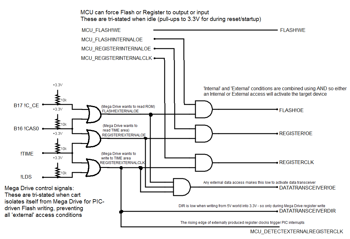
A valid ROM read action occurs when the Mega Drive is reading data or instructions from the currently selected Flash partition as if it were an ordinary cartridge game. It is determined by FLASH!EXTERNALOE = CART!C_CE + CART!C_OE. When this occurs, the Data Bus directionality is set to 3.3V -> 5V and is enabled. This places the 16-bit data value output by the Flash IC onto the EDGE data output bus to be read by the Mega Drive. Register: The 16-bit register is used to allow two-way communication from the Mega Drive to the Game Raccoon board. The register is written to when a write to the !TIME address space is performed by the 68000 processor in the Mega Drive. Both the PIC and 68000 processor can read and write the contents of the register. A valid !TIME write occurs when the Game Raccoon boot firmware running from the Mega Drive's RAM communicates with the Game Raccoon board. It is determined by REGISTEREXTERNALCLK = CART!TIME + CART!LDS. When the write finishes (the strobe ends and the register stores the value), the PIC detects the change in the D-type register's clock signal, allowing the PIC to awaken and isolate the Game Raccoon from the bus, making the bus available for the PIC to read the value. This exchange is necessary since the PIC would almost certainly not be able to react in time to read the value from the data bus itself when the 68000 performs the write: the register allows the written value to be replayed and read back slower by the PIC. All external !TIME write actions cause the Game Raccoon to isolate itself from the bus (since this is necessary to allow the register to be read using the internal data bus). The 68000-side menu firmware polls the cartridge to detect the end of isolation. 
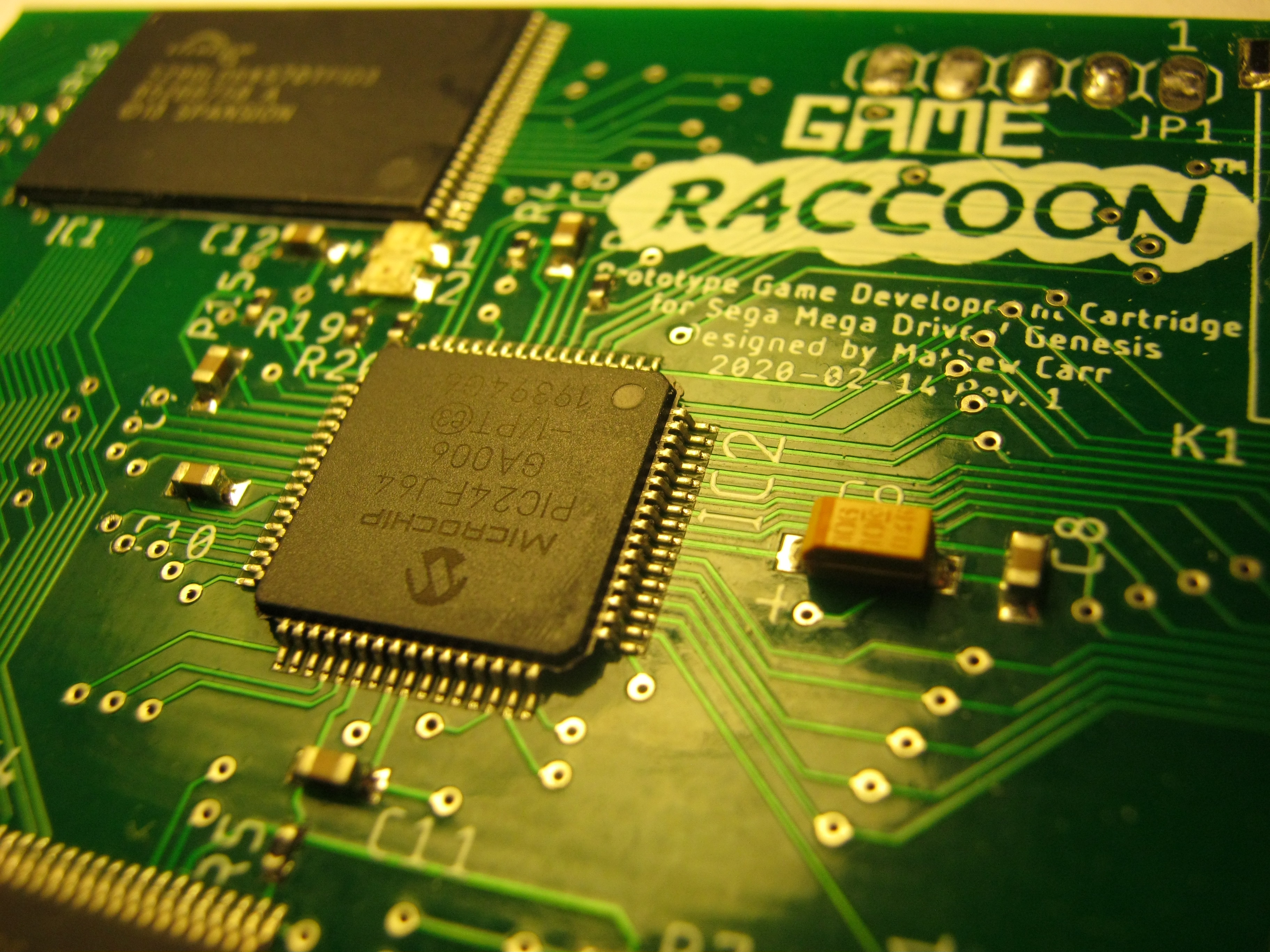
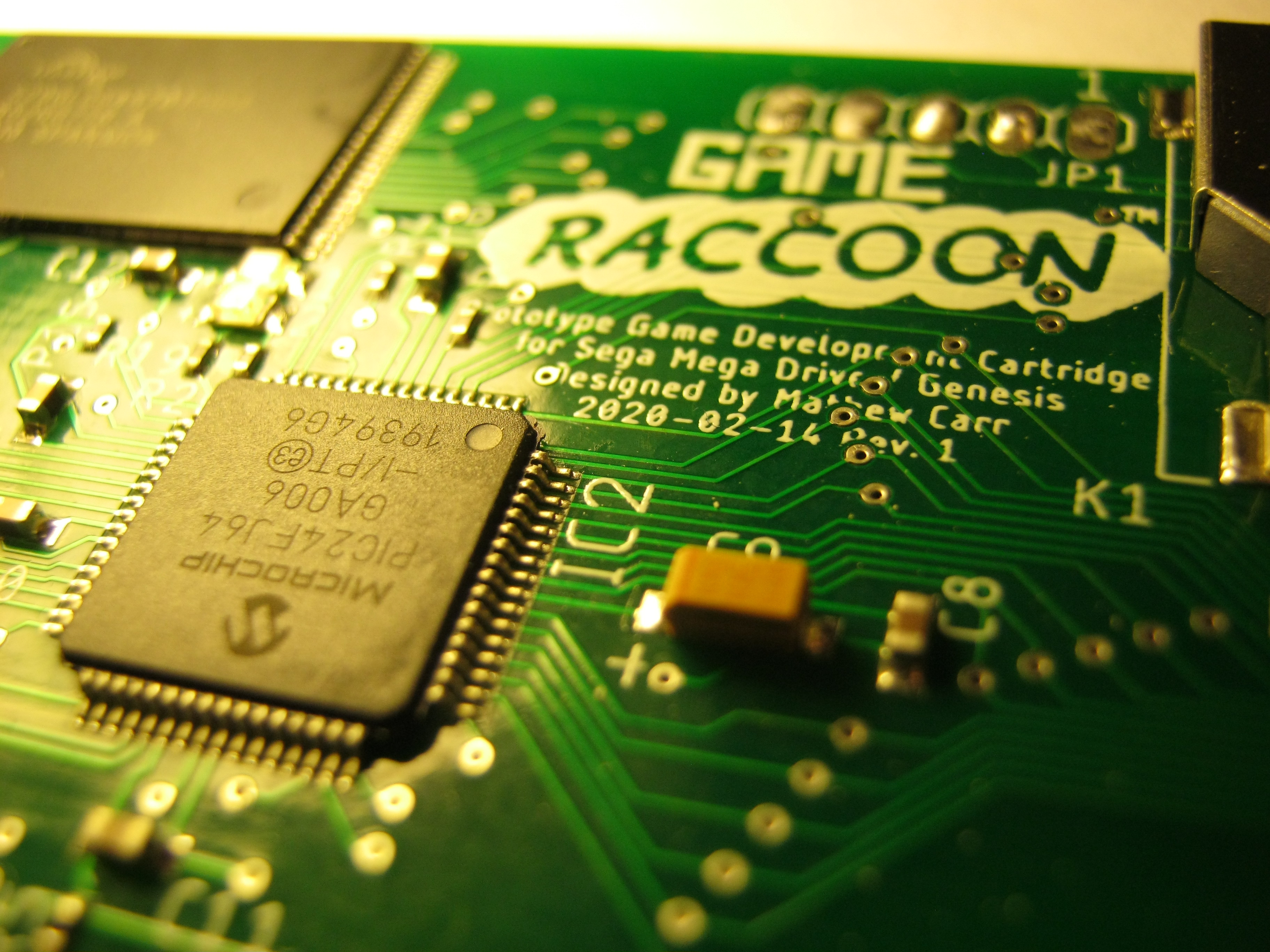
PIC microcontroller and SD card: 
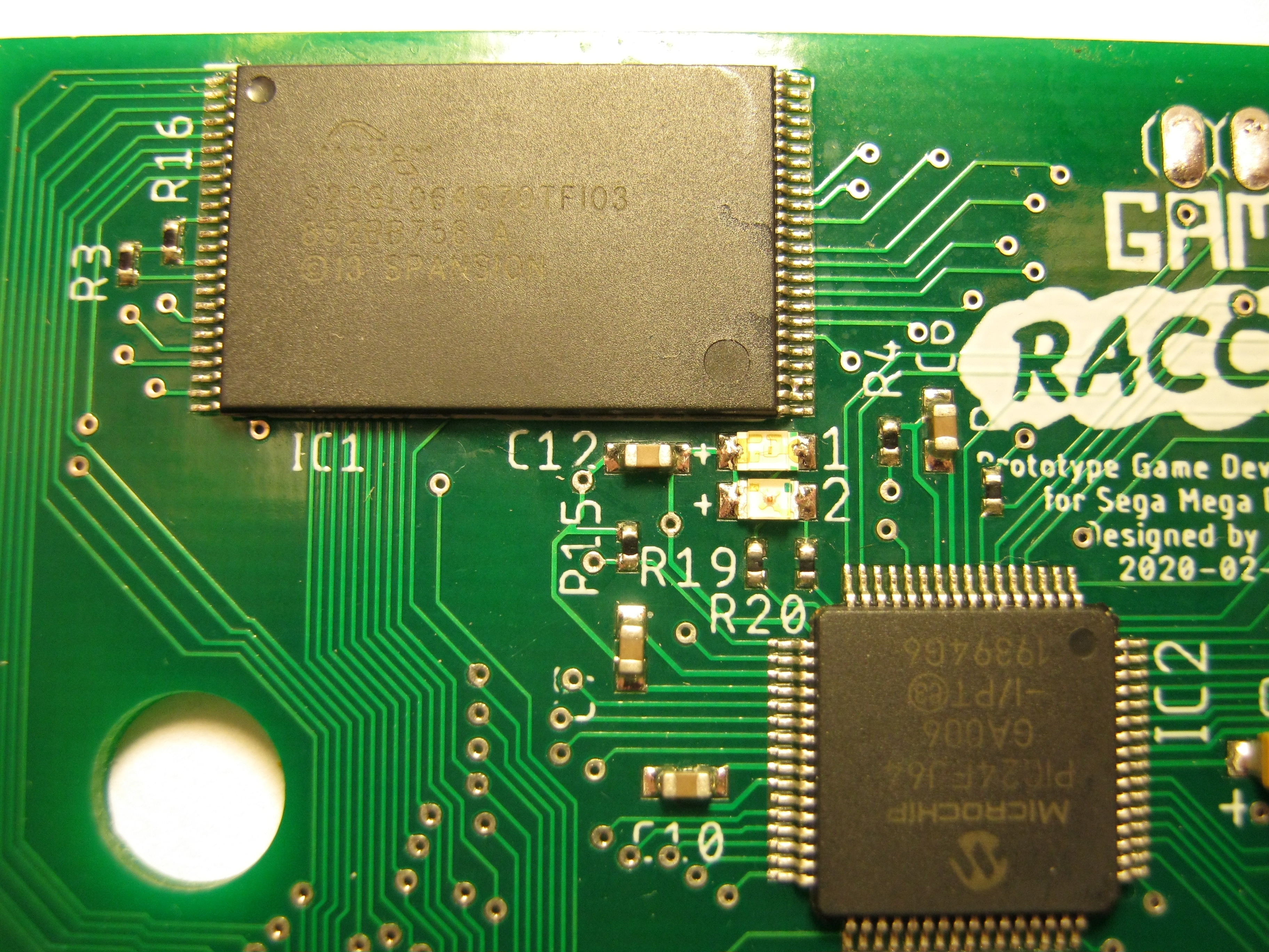
The PIC24FJ64GA006 microcontroller provides all the 'intelligence' of the Game Raccoon cartridge. The PIC responds to commands from the Mega Drive, and can isolate the Game Raccoon from the Mega Drive to allow it to read ROM images from the SD card and write them to the Flash. It also reads the full directory structure of the SD card and writes this to the directory cache in the BOOT partition. The PIC firmware provides the functional brains of the Game Raccoon. It is written in C and compiled using xc16 in Microchip MPLAB. 
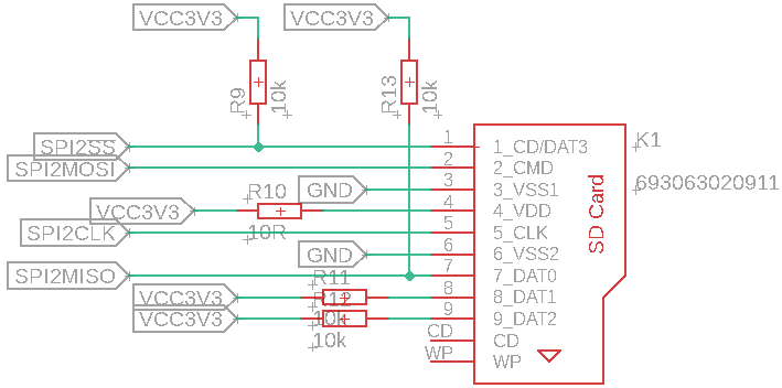
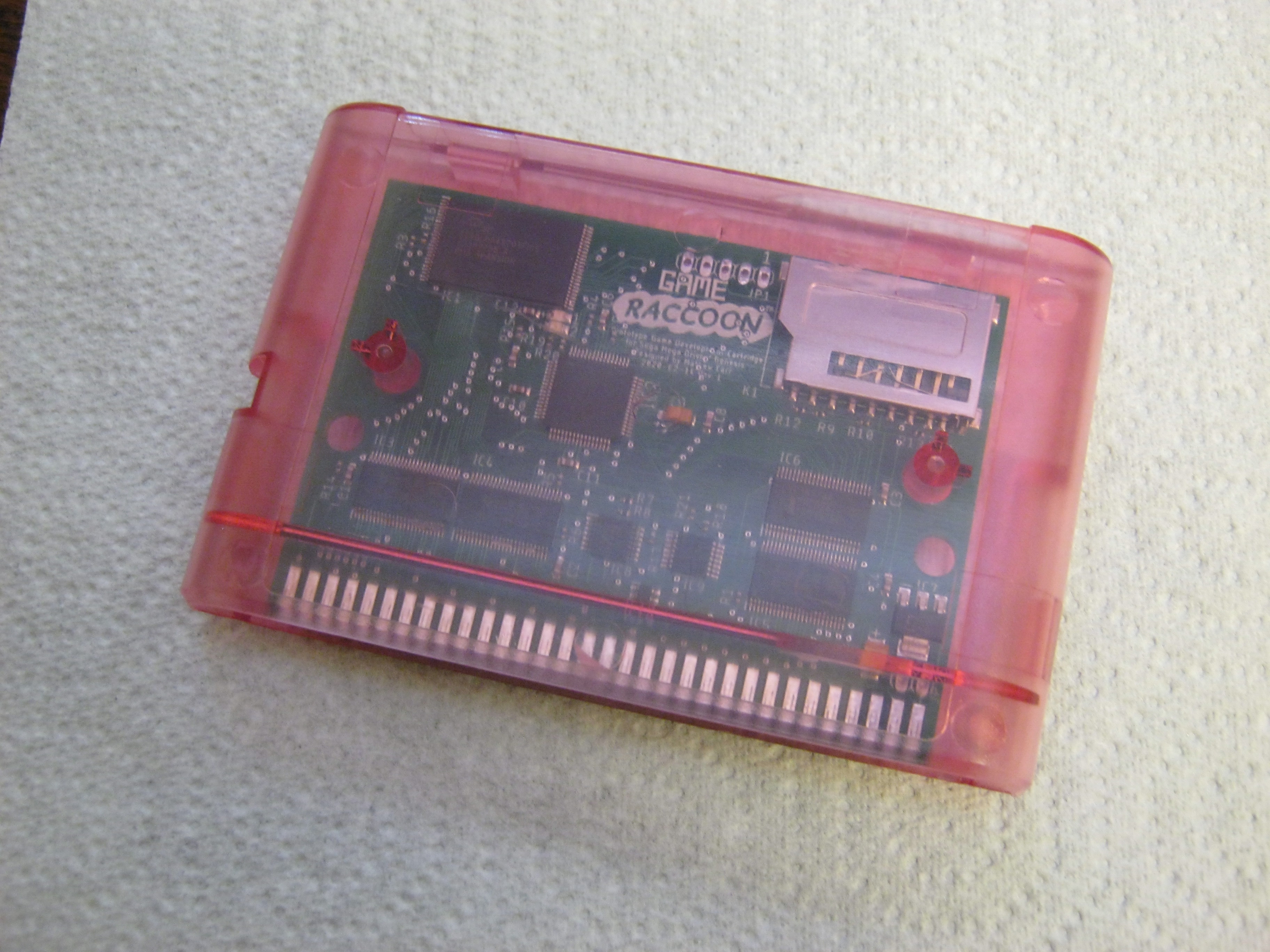
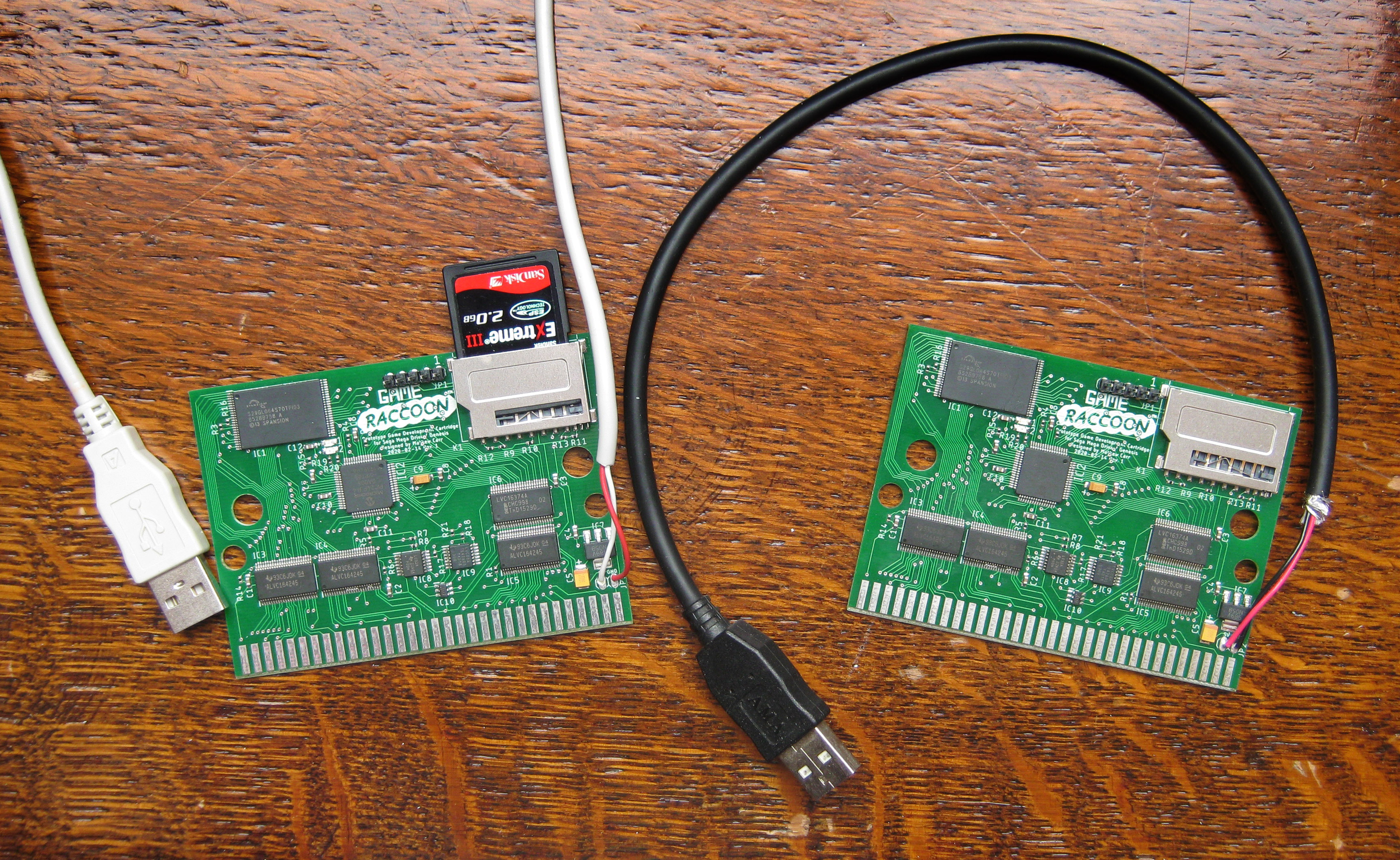
The SD card socket provides storage of game or firmware images to be installed onto the Game Raccoon's Flash partitions. The PIC communicates with the SD card using SPI channel 2. The part number is WURTH 693063020911 (it took some searching to find this!) and is wired as shown. The 10R resistor is to prevent large inrush currents (as I was told, at least) during power-on (or if you're gutsy enough to remove the SD card while power is on?!?). I used FatFs - Generic FAT Filesystem Module R0.14 with the PIC24 SPI reference driver to communicate with the SD card. It's necessary to modify several constants and functions in FatFs to get it to work with the Game Raccoon board - specifically, it needs to be set to SPI2, have the card insertion detection and write protection detection functions forced, and the correct internal tick timer interrupt supplied. Surprisingly, it all seemed to work first time! (There is a lot about this in Adventure 0.) Flash: 
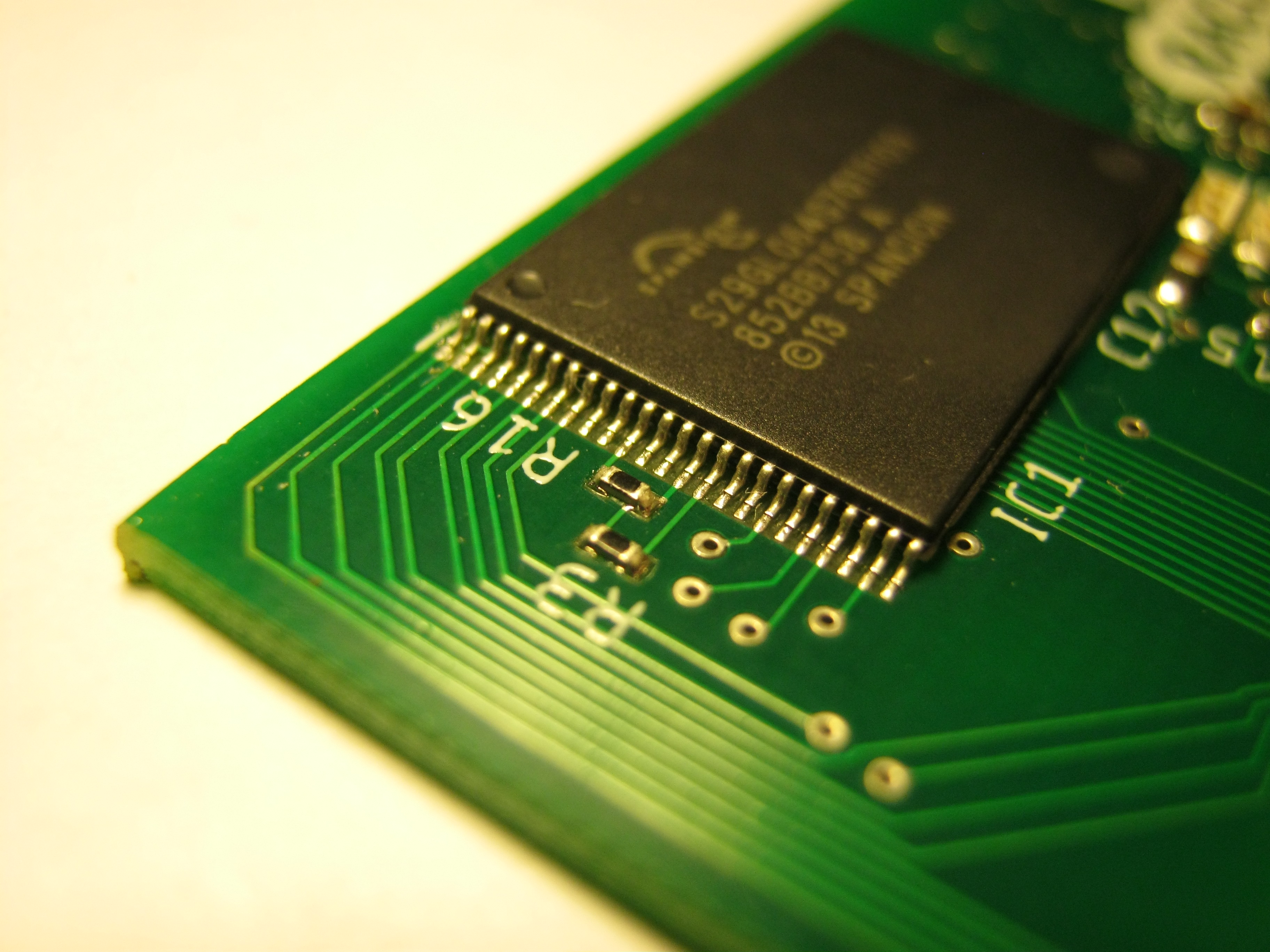
As the Mega Drive system supports a 4 megabyte address space for game cartridges, an 8 megabyte Flash IC is used to store a 4 megabyte BOOT partition which is bankswitched in on boot containing the menu firmware, and a 4 megabyte GAME partition into which the game images are written. The Flash IC provides 8 megabytes of non-volatile storage with a 16-bit wide data bus, and is conceptually divided two 4 megabyte halves, controlled by the highest address line A21. (There are 22 address lines A0-A21 on the Flash, providing 4 megawords of storage.) The partitions are simply flat 4 megabyte regions of the Flash memory, not filesystems. At any time, either the lower BOOT or upper GAME partition is active: the A21 line of the Flash is referred to as !BOOT/GAME, and it acts as a flag enabling one partition or the other. This signal is pulled down by a resistor, which means that when the Mega Drive is powered on, the BOOT partition is immediately activated, and remains this way until the PIC changes its FLASH!GAME/BOOT signal from input to output to override this value. 
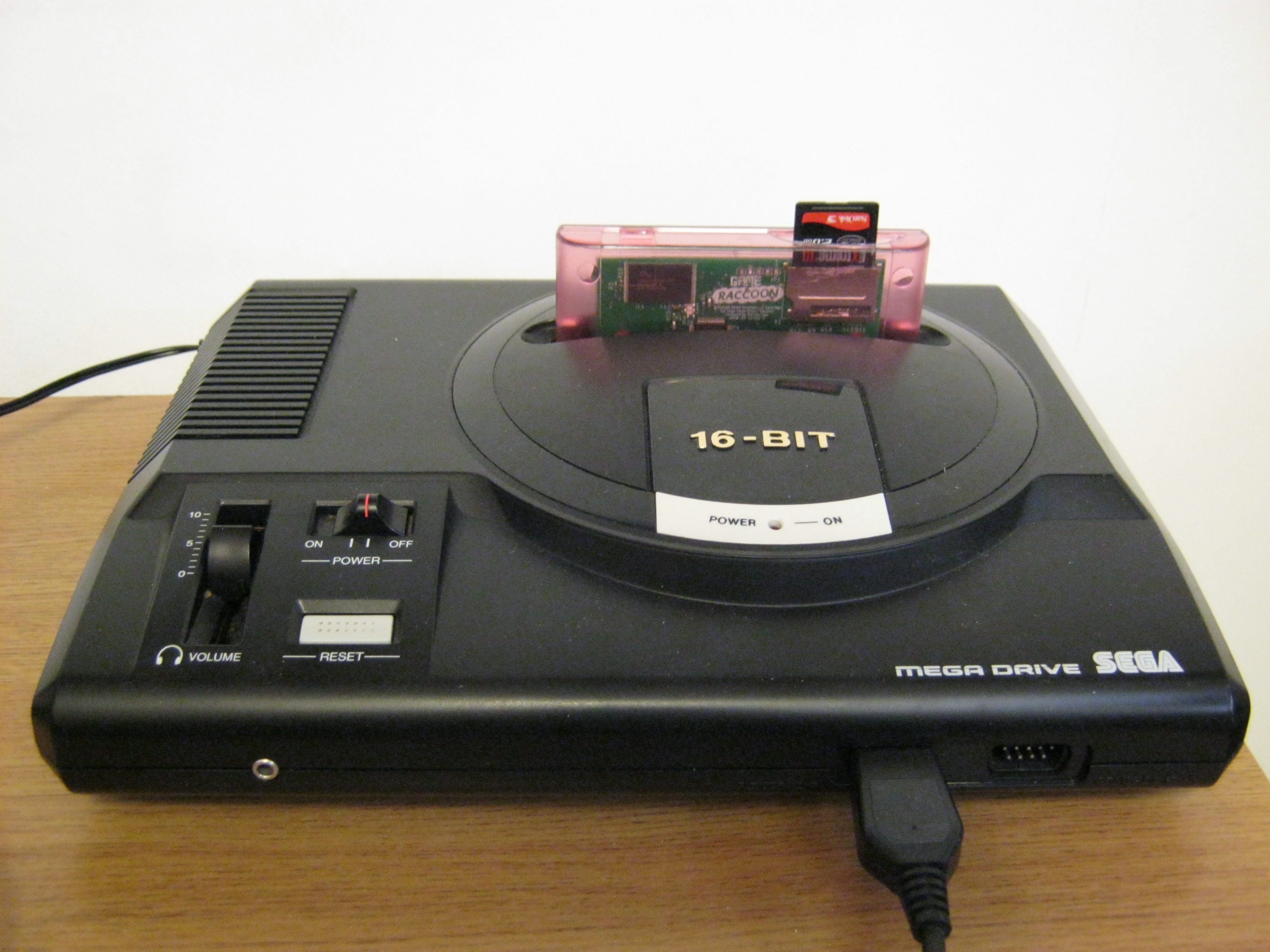
The Flash firmware provides the user-facing interactive part of the Game Raccoon. It is written in 68000 assembly language and assembled using Bruce Tomlin's asmx and a Python makefile-like system. This firmware provides the menu system allowing the user to select a game to install, and boot the currently installed game. When the Mega Drive is turned on, the Game Raccoon's signalling acts as a 4 megabyte ROM cartridge providing the contents of the BOOT partition at the $000000 to $3FFFFF address range, allowing the Mega Drive to boot into the Game Raccoon's Flash-resident firmware. (Since !C_CE is used to chip select the Flash, this range should automatically migrate to $400000 to $7FFFFF if a Mega CD is installed, but I haven't tested this.) Voltage regulator: All devices on the board are powered by a LM1117 3.3V linear voltage regulator, converting the 5V power supplied by the Mega Drive into 3.3V used by all the components on the Game Raccoon PCB, as well as the SD card socket. Internally, the Game Raccoon uses 3.3V signalling (LVC logic family) between all its components. Adjacent to the voltage regulator are two pads connected to the 5V and Ground nets. These allow an auxiliary 5V power supply (such as a USB-compatible wall wart) to be connected to the Game Raccoon, allowing it to be externally fully powered when not installed within a Mega Drive during programming or debugging. PICKIT programmer: At the top of the Game Raccoon PCB are pads to mount a five pin 0.1 inch header. These pins correspond with pins 1-5 of a PICKIT 2 programmer/debugger: !MCLR, 3.3V, GND, DATA and CLOCK. Pin 1 is closest to the SD card socket and is marked on the silkscreen. To program or debug the Game Raccoon's PIC, connect a PICKIT 2 to these pins using DuPont jump leads. And in turn, program the BOOT partition of the Flash by uploading a debug firmware that does nothing but immediately isolate the bus and write the contents of some binary file on the SD card to the BOOT partition. When you do this, don't forget to reupload the normal reactive Game Raccoon PIC firmware when you're done. :D I wouldn't recommend using the PICKIT 2 when external 5V power is not supplied - this would entail operating the dual supply transceivers with only a 3.3V supply connected. Indicators: Two surface mounted indicator LEDs are controlled by the Game Raccoon PIC firmware to provide generic signalling back to the user/programmer. Various blink sequences can be defined to communicate the current condition when the Game Raccoon is used in a Mega Drive and therefore it wouldn't be safe to have the debugger also connected. The values of the series resistors are chosen to reduce the active current to approximately 5mA per LED during operation (using the forward voltage/current graphs in the LED datasheets). As it happens, the mega bright blue LED consumes 2mA, while the somewhat dull green LED consumes 7mA (tested by grounding the MCU-facing side of the resistor through an ammeter).

Theory of Operation

Commands are sent from the 68000 to the PIC, and result codes returned from the PIC to the 68000 through the bidirectional register mapped to the !TIME address space. A command is sent by the 68000, the PIC reacts then disengages isolation, potentially storing a return code first: 1) The PIC state begins idle, with a Change Notification interrupt active on REGISTEREXTERNALCLK to detect changes in the register write clock caused by !TIME write accesses from the 68000. 2) The 68000 writes a word value to $A13000, then NOPs briefly, then continually reads $000006.w and loops continually while the LSB is set. 3) The PIC is awakened by the change in state on the register clock. It waits momentarily for the write to complete, then engages isolation by setting !68000 high, disabling all the transceivers, allowing the PIC control over the internal address and data buses. Since D0 is pulled up by the cart, any word reads by the Mega Drive to cart space will have their LSB set (other bits indeterminate). Since I know that the lowest bit of $06.w will be zero (since this is the entry point vector in the header, it must be a valid word address with LSB = 0), the 68000 stub will continually read 1 in the LSB of $06.w while isolated and 0 when the cart is non-isolated. 4) The PIC reads the value from the register using the internal buses, and acts upon the value. 5) After the operation is complete, the PIC may write a 16-bit value into the register for the 68000 to read later. 6) The PIC re-engages the Change Notification interrupt and lowers !68000 to disengage isolation. 7) The 68000's busy loop ends now that it can read the expected low bit, and it is free to read the return code or act further. On boot, the Game Raccoon acts as a 4 megabyte Mask ROM containing the Game Raccoon menu firmware. The ability to communicate with the PIC allows the menu to request that information about the current contents of the SD card be made available to it, and that a given image be written into the GAME partition, or that the GAME partition be bankswitched in in preparation for launching the installed game image: 1) On boot or reset, !VRES is asserted, then negated, resetting the PIC and Flash. The default state of cart isolation is disengaged. The cart starts connected to the 68000 address and data buses. The MCU sets up a Change Notification interrupt on REGISTEREXTERNALCLK, then idles. The power-on state of !BOOT/GAME is to bankswitch in the lower 4 megabyte BOOT partition of the Flash containing the bootstrap code. 2) The Mega Drive performs the normal boot/TMSS sequence reading from the lower 4MByte of the Flash, and then boots into the set-up sequence of the Game Raccoon cart's firmware. 3) The controller is polled to detect whether the 'emergency boot' is requested. If so, no data is copied to the VDP and the current game image boots immediately using the boot sequence described below. 4) The RAM-resident Game Raccoon menu is copied to the Mega Drive RAM. The graphics are copied into the VDP and the menu operation begins executing from RAM so it may continue during isolation. 5) A handshake command is traded with the PIC to check for the presence of the SD card and attempt to mount it. If successful, it reads the root directory to verify the card is non-empty and contains a valid filesystem. The result code is stored in the bidirectional register. 6) The menu allows the user to select Boot, Browse or About. 7) If Browse is selected, a command is sent to the PIC to cause the directory record cache to be regenerated: 8) The PIC reads the filenames and directory structure from the SD card and uses FLASH!WE, the cart address and data buses to write the retrieved data to a reserved block within the BOOT partition of the Flash. 9) When this operation is complete with a valid result code, all the available games' data will be available within the reserved block of Flash, accessible as if it were always present within the cartridge ROM. 10) The user selects a game - this is encoded as a 16-bit command value and sent to the PIC. Game image command values are simply the index of the game in the directory record cache and take values below $FFF0. 11) The MCU raises !BOOT/GAME to switch in the upper 4MByte of the Flash. The MCU can now open the indicated game file from the SD card and write it to the upper 4MByte of Flash. !BOOT/GAME is set back to BOOT to allow the menu to resume operation browsing the directory record cache after the isolation is complete. 12) The user can now select Boot, sending a command to the PIC. 13) To Boot the currently selected game, the PIC bankswitches in the GAME partition and returns. When done, the MCU enters a low-power idle state and takes no further action until the next system reset. All of its pins are inputs except !BOOT/GAME which is high. 14) The Mega Drive cleans up the RAM and VRAM states and uninstalls the Game Raccoon RAM-resident menu from RAM using an anti-bootstrap, then jumps to $04.l to boot the game present in the upper 4MByte of the Flash. From this point on, the cart is completely dumb ROM. Writes to !TIME will populate the register, but it will never be read - games that use save SRAM will read garbage from !TIME and bankswitching to SRAM will silently fail.

Logic section design

There are three external conditions that the Mega Drive can push towards the Game Raccoon: • A read from mask ROM. This occurs when B17 !CE_0 and B16 !CAS0 are both low. • A read from the register. This occurs when B31 !TIME and B16 !CAS0 are both low. • A write to the register. This occurs when B31 !TIME is low and either B28 !LWR or B29 !UWR are low. All writes to the Game Raccoon register ought to be word writes though. The fourth condition combination, a write to mask ROM, is ignored. Detecting these conditions to produce an active-low condition signal is done with an OR gate. • FLASH!EXTERNALOE = !CE_0 + !CAS0REGISTER!EXTERNALOE = !TIME + !CAS0REGISTEREXTERNALCLK = !TIME + (!LWR * !UWR) These are entirely different to the conditions detected by the Revision 0 board! Since the two byte write strobes are independent, and I know that any access to the Game Raccoon's register will always be word-sized, I can detect the register write by only monitoring one of the strobes, so !UWR is not needed. The PIC can perform these three actions as well, requiring an AND stage to allow the PIC to force any of these three active-low enables to be asserted. Each of the overrides is a GPIO pin on the MCU pulled up by default. The MCU needs to detect register write activity triggered by the Mega Drive, so the computed REGISTEREXTERNALCLK condition is routed to the PIC. • FLASH!OE = FLASH!EXTERNALOE AND MCU!FLASHFORCEOEREGISTER!OE = REGISTER!EXTERNALOE AND MCU!REGISTERFORCEOEREGISTERCLK = REGISTEREXTERNALCLK AND MCUREGISTERINTERNALCLK The address and signals transceiver directionality is always 5V -> 3.3V, never outputting from the cartridge onto the Mega Drive's address bus; and the enable is MCU!68000, allowing the Mega Drive's bus state to be reproduced inside the cart unless isolation is in effect. The data transceiver's conditions are vastly different to Revision 0: • An external read from mask ROM. The cartridge should output a value to the Mega Drive. • An external read from the register. The cartridge should output a value to the Mega Drive. • An external write to the register. The cartridge should receive a value from the Mega Drive. In all other states, the data transceiver should be idle. This means that when any of the three external conditions are active, DATATRANSCEIVER!OE should be low. • DATATRANSCEIVER!OE = FLASH!EXTERNALOE AND REGISTER!EXTERNALOE AND REGISTEREXTERNALCLK The directionality should be 3.3V -> 5V always, except when an external register write is taking place. This means that DATATRANSCEIVERDIR should be High almost always, and Low only when REGISTEREXTERNALCLK is Low. • DATATRANSCEIVERDIR = REGISTEREXTERNALCLK MCU Outputs: While the MCU is in the reset state, all its pins are tristated. My pull- resistors need to make this a good safe state for the cart to be in before the menu begins, and while the real game is running and the MCU is idle: • MCU!BOOT/GAME, low default, if low select the boot menu half of Flash, if high select the game half of Flash. • MCU_FLASH!WE, high default, allows the MCU to program the Flash. • MCU!68000, low default, if high the cartridge transceivers tristate the cart from the 68000 buses. • MCU_FLASH!INTERNALOE, high default, if low the MCU is reading the Flash (to verify a write). • MCU_REGISTER!INTERNALOE, high default, if low the MCU is reading the last value written to a !TIME address. • MCU_REGISTERINTERNALCLK, high default, if low the MCU is writing the current contents of the data bus to the register for the 68000 to read from !TIME later. • !LEDBLUE, high Z default, open-drain LED indicator pin. • !LEDGREEN, high Z default, open-drain LED indicator pin. MCU Inputs: • !RESET, standard reset. • FLASHREADY, active-high, pulled low by Flash during Busy. This time the Flash can correctly indicate when it is unavailable for further communication due to being busy formatting a sector or some other action is taking place! • REGISTEREXTERNALCLK, an edge wakes the PIC to respond to a command.

Game Raccoon Revision 1 Downloads

These are presented for your own personal use for educational, research and informative purposes. You use any of the information, designs, layouts or software included here at your own risk. Licenses may change with future revisions. The licensor and copyright holder is Mathew Carr, my email address is at the bottom of this web page. This license does not grant you rights to use any copyright holder or any other party's name, logo, or trademarks, such as the Game Raccoon name, logo, trademark or character. Where third-party items have been included, modifications may have been used to adapt these to the project. The original authors of third-party inclusions do not offer support for these items. Software: The following downloads are offered under the Affero General Public License Version 3 with Additional Terms. You can read this license here. The license and licensing notices are included in each of the zip files below. 2020_07_07_game_raccoon_revision_1_68kasm.zip Revision 1: Source code and binary image for the BOOT partition of the Game Raccoon, containing the menu system and handshaking necessary to browse, install and begin games. asmx is required to assemble the ROM image. 2020_07_07_distributionRevision1PIC_GameRaccoon.X.zip Revision 1: Source code and binary image for the PIC of the Game Raccoon, containing the flow to interact with the boot menu using isolation and transferring to the game partition; and all the routines for interacting with the SD card and Flash memory: scanning the directory tree and writing the directory record cache, and erasing and programming the Flash. Includes FatFs - Generic FAT Filesystem Module R0.14 modified for PIC24 on SPI2. Use Microchip MPLAB IDE and xc16 to compile the firmware image. Hardware: The following downloads are offered under the CERN Open Hardware Licence Version 2 - Strongly Reciprocal. You can read this license here. The license and licensing notices are included in each of the zip files below. 2020_07_02_GameRaccoonRevision1_EAGLE.zip. Revision 1: EAGLE Schematic and Board layout for EAGLE 9.4.2. GAMERACCOON_Revision1_gerbers_2020-02-14.zip Revision 1: Gerber files zipped together. Use 1.6mm thickness. Edge bevelling for the connector if you can get it. From my PCBWAY dashboard, the settings I chose were: "61x84mm 2 Layers, Thickness:1.6 mm, Finished Copper:1, Surface Finish:HASL lead free, Material: FR-4 TG130, Via Process: Tenting vias, Finished Copper: 1 oz Cu" 20200214_revision1_schematicfinal.png 20200214_revision1_boardfinal.png 20200214_revision1_boardfinal2.png 20200214_revision1_gameraccoon_board_orientationguide.png Revision 1: Schematic, board image and pick and place orientation verification image. 2020_07_02_PNP_BOM_GameRaccoonRevision1.zip Revision 1: Bill of Materials and Pick and Place file for components used in Game Raccoon Revision 1 manufacture. Always get visual confirmation of the layout from your manufacturer before committing to an order. Additional files: The following third-party files are offered for convenience, and are not copyright Mathew Carr: 2020_07_07_asmx-2.0b5.zip asmx assembler source, with .exe for assembling for 68k. 2020_07_02_GameRaccoonRevision1_eagle_component_libs.zip Revision 1: Collection of EAGLE part libraries (mostly from eagle.componentsearchengine.com) used in Game Raccoon Revision 1 board. Also includes Bruce Tomlin's cartridge PCB library. Datasheets for components, etc.

Manufacturing and pre-set-up

After fabricating and populating the Game Raccoon Revision 1 PCB, it's necessary to install both the PIC firmware and the Flash firmware for the cartridge to be functional. The process for installing a new firmware to the PIC is as follows: • You will need MPLAB X installed with the xc16 compiler. This is available for no cost for Windows, Mac or Linux users. • Do not attempt to update the PIC firmware while the Game Raccoon is inserted in a Mega Drive. Always remove the board and lay it on your workbench beside your PC. The board must be powered externally through the auxiliary power supply header while working on the PIC. • Solder on a pair of cables to the auxiliary power supply header JP2. This must connect to a 5V DC supply, such as a USB cable. I use a USB cable and wall-wart for this purpose. • Solder on a 5-pin 0.1 inch pin header to JP1. Alternatively, you can solder on a DuPont-style ribbon cable if you need to. • Connect a compatible PICKIT programmer such as a PICKIT 2 to the 5-pin header using a cable. • Power on the Game Raccoon PCB through the 5V supply. • Open the Game Raccoon PIC firmware project in MPLAB X. • Recompile the firmware image as per your needs. • Upload the firmware image to the PIC from the IDE while the PCB is powered externally. The firmware source file main.c is set up to compile the firmware image that follows the normal Game Raccoon menu flow. To debug the Game Raccoon or force-install an image into either the BOOT or GAME partitions, it is necessary to recompile the firmware with the following #defines set: #define DEBUG_WRITE_IMAGE "game_raccoon_boot_image_directory_cache.bin" #define DEBUG_WRITE_IMAGE_PARTITION FLASH_PARTITION_BOOT This will produce a firmware that, when powered-up, will immediately isolate the bus and begin writing the file given by DEBUG_WRITE_IMAGE from the SD card to the Flash partition. When complete, the indicator lights will pulse slowly back and forth. It is advisable to verify the image was correctly written before proceeding. You can edit main.c to write the current contents of either Flash partition to a file on the SD card for debugging purposes. To install the normal Game Raccoon intelligent command-reactive behaviour, you must recompile the firmware and with the changes reversed and upload this into the PIC after writing the menu firmware to the Flash. If you don't, the Game Raccoon will attempt the Flash write every time it is powered on! - If you want you can use this method to install different PIC firmwares with additional functions. An example of this is if you want to attempt writing a game that can access the SD card to store options, scores or other data. It would be possible to write a game that can load additional data into the Flash at run-time: if you want to create a massive game with multiple independent stages. The Game Raccoon menu firmware itself is a game image that requests the PIC rewrite the contents of the GAME partition, after all. To achieve this, you'd have to modify the PIC firmware with new commands that rewrote the contents of the Flash with the appropriate data from the SD card. This would require other players to have a Game Raccoon with a PIC running the same firmware, so it's not advisable, or supported! - Use python fruitsalad.py complete_boot_rom_image to assemble the 68k Flash-resident BOOT ROM image. Open the various .py and .68k.asm files to understand the stages involved in assembling and linking the image. game_raccoon_boot_image_directory_cache.bin is suitable to write to the lower partition. The file go.bat completely assembles this file and copies it as GAME_RACCOON_UPDATE.BIN. If there is a functioning Game Raccoon menu firmware on your cartridge, you can update it from the Mega Drive without having to use a PICKIT. This is done at your own risk. To do this, perform the following steps: • Turn off your Mega Drive and remove the SD card from the Game Raccoon cartridge. • Copy GAME_RACCOON_UPDATE.BIN to the root of the SD card using your PC. • Reinsert the SD card. • Boot the Game Raccoon on your Mega Drive as normal. • On the main title screen, press C to enter the About screen. • On the About screen, hold Start for five seconds. • You will be presented with a warning screen. Read it. • If you accept the conditions and understand the process, follow the on-screen prompts to proceed. • Wait for the installation process to complete. • When the installation is complete, turn off your Mega Drive. • The menu is now installed. This process completely overwrites the BOOT partition of the Game Raccoon with the contents of GAME_RACCOON_UPDATE.BIN. If this file is not present, the installation aborts without changes. If the file is corrupt or contains something other than a valid Game Raccoon 68k menu firmware image, you will need to manually reprogram the Flash-resident firmware through the PIC using a PICKIT as described previously. - The Game Raccoon Revision 1 PCB fits inside a standard PAL Mega Drive cartridge shell, or a third-party replacement such as those sold through AliExpress, such as the transparent red cartridge shown in the above photographs. You can see in these photographs that the Game Raccoon PCB has multiple sets of screw holes to match the first-party Sega style cartridges as well as the EA style cartridges. Note that any cartridge shell you choose must have a slot in the upper right top face to accomodate the SD card. The Game Raccoon does still function without an SD card if you want to use it in this configuration. To assemble the shell around the cartridge PCB, you will need to accomodate the 5-pin PICKIT programming header. Typically, once the PIC firmware is installed and the BOOT partition is ready, these pins are no longer needed and can be desoldered. The auxiliary power supply should also be desoldered before the cartridge shell is assembled. Do not power the Game Raccoon on through the Mega Drive while either the auxiliary power supply or a PICKIT is connected. Always verify that the 5-pin header is bare, if present, and that the auxiliary power supply is not plugged into a wall-wart or PC.

Cartridge Availability

At the time of writing (July 2020) I do not manufacture or sell Game Raccoon Revision 1 completed cartridges or bare boards. If you want a Game Raccoon, you will have to arrange for manufacture, assembly and programming yourself. If you do so, no support is offered. For Game Raccoon news, it's best to follow my personal twitter account @SkullKidUK.

Design Q&A

Why is Flash used and not SRAM? Nonvolatile storage is necessary for the Mega Drive to boot into. Merging the role of the non-volatile boot region and the rewritable game partition into a single device simplifies the design greatly. The disadvantages of this approach are that the Flash erasure and writing process is significantly slower than SRAM writing, but since the PIC is likely to be somewhat slow anyway, I don't care. I'm used to cassette tapes. :D Flash also has a limited lifetime. The datasheet for the S29GL064S Flash IC chosen quotes a '100,000 Erase Cycles per Sector Minimum'. Since the Game Raccoon doesn't contain any sector mapping hardware and presents the upper 4 megabytes containing the game as a single contiguous region, the lowest sector of the game partition will necessarily be erased every time a new ROM image is installed into it. This means that you'll get a minimum maximum of 100,000 game installations before the cartridge may malfunction irreperably. If you were testing a game and wrote 20 game images per day, every day, the Game Raccoon would last 13.7 years. If you were playing Mobius Evolution and wrote one game image per week and played that one installed game off-and-on, you'd get 1923 years out of a Game Raccoon. Either way, I think the Mega Drive itself would fail before the cart did. The advantage of this is that the last installed game will be immediately available on the cartridge without any further SD card access. On an intent level, the act of installing a game onto the cartridge makes more sense to me anyway. Why is a PIC used? The PIC combines the roles of SD card interface, Flash interface and intelligent behaviour. The model of PIC used was chosen because it was available in the parts catalogue of the original intended manufacturer, as well as being compatible with the PICKIT 2 programmer I own. It's inexpensive, functional, mass-produced, and allows the developer to reprogram the behaviour of their PIC in C if they choose, to upgrade the SD card support or add additional functions. Why aren't saves supported? To answer this, consider what would be needed to support saves. There isn't a single set method by which games support saving; it's possible for a game to attempt to save by any means the author can conceive. Most of these ways involve the !TIME address space, which the Raccoon uses for communication. Adding FeRAM/FRAM for battery-free, non-volatile, SRAM-like saving would require yet another device on the internal buses beside the Flash and the PIC and would make one heck of a mess to route.

Design Evaluation

The Game Raccoon Revision 1 has high compatibility with all retail images that I'm able to access. The compatibility with demoscene productions, homebrew games and Sonic the Hedgehog hacks available from SEGA through Steam Workshop are very high. More about compatibility can be found in Adventure 1. All the issues with Revision 0 as listed in the previous Technical Report have been solved entirely!

Pending Issues

No animated cute raccoon mascot! I need to hire an artist to animate me a Game Raccoon, can you help?

Notices

/*----------------------------------------------------------------------------/
/  FatFs - Generic FAT Filesystem Module  R0.14                               /
/-----------------------------------------------------------------------------/
/
/ Copyright (C) 2019, ChaN, all right reserved.
/
/ FatFs module is an open source software. Redistribution and use of FatFs in
/ source and binary forms, with or without modification, are permitted provided
/ that the following condition is met:
/
/ 1. Redistributions of source code must retain the above copyright notice,
/    this condition and the following disclaimer.
/
/ This software is provided by the copyright holder and contributors "AS IS"
/ and any warranties related to this software are DISCLAIMED.
/ The copyright owner or contributors be NOT LIABLE for any damages caused
/ by use of this software.
/----------------------------------------------------------------------------*/
'Gsmplay_8x16.png' font designed by Damian Yerrick, released under CC0
Saikyo Sans and Torus Sans fonts designed by usr_share, released under CC0

https://opengameart.org/content/a-package-of-8-bit-fonts-for-grafx2-and-linux
    Special thanks to:
     Cearn,Charles MacDonald,Chilly Willy,
     Consolemad, Kabuto,oerg866,raq, Sik,
     Stef, Steve Snake, Tepples, TmEE,
     VAdaPEGA.
   
    Greets to:
     Fizzer, GoBusto, Mungojerrie,
     The Sanctum, YakYak, SpritesMind,
     #uplink, #uberducks,
     and all those who follow the Raccoon!
This information is provided for education, research and informative purposes.