

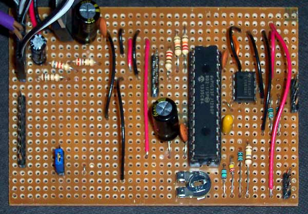

The Ocelot mainboard can be split into a number of areas each with a distinct function.
Power supply - Top left. Connects to the battery housing, power switch, filtering and regulation stages.
System and debugging - Top left under power supply. Connects to reset switch, reset switch debouncing, power and status LEDs, PICkit 2 header and supply voltage measurement.
Input bus - Bottom left. Connects the front panel JOYSTICK port to the GPIO pins of the dsPIC33.
DAC output - Top right. Connects the reference voltage generator and the SPI bus of the dsPIC33 to the TLV5618A chip, and to the X/Y connectors.
PSG network - Bottom right. Resistor network converting four GPIO pin voltage output values into analogue value, connected to adjustment trimmer and to audio board pin header.
Microchip dsPIC33FJ128GP802, running at 39.6 MIPS. 128kByte PROM, 16kByte RAM. 28-pin DIP 0.3 inch wide, 0.1 inch pitch configuration.
See Microchip product page for more details.
The Ocelot kernel interfaces the dsPIC33 with the components mounted on the Ocelot mainboard, elevating the microcontroller to part of an integrated arcade system.
The core of the runtime provides low-level services to set up and manage the dsPIC33 state. The DAC instruction buffering system allows points and lines to be collected and output through the DAC to the oscilloscope interface. The I/O system reads Amiga/Atari joystick or Master System/Mega Drive pad state connected through the front panel.
I have created additional modules including a 4-channel polyphonic synthesizer, 3 bit 8 kHz waveform playback DAC, 2D graphics and tweened animation library, and 3D wireframe graphics library ('world').
7 pin bi-directional interface of dsPIC33 wired to a pin header, connected to case via ribbon to a male DE-9 connector on the front panel.
Software controlled by the Ocelot runtime. Compatible with Amiga joysticks (such as the estimable Zipstik), Master System 2 button pad and Mega Drive 3 and 6 button pads. The Ocelot runtime can detect the presence of the Mega Drive pad and correctly supply the button-reading-toggle signal, decoding the multiple pages.
Amiga/Atari 9-pin joyticks are supported using dsPIC33 internal pull-up mode, treading the pins as active-low inputs that close to ground when depressed.
3.3V filtered voltage is supplied through 9-pin JOYSTICK connector on front panel to supply power to Mega Drive pad multiplexer chip or Atari potentiometer dial conroller. Internal jumper can route the Vcc line to different pins to support different devices. (Untested for potentiometer-based controllers like paddles!)
Texas Instruments TLV5618A DAC outputs voltages in range 0V-1.94V, which are exposed on Ocelot board as a 4-pin header. These are connected to a pair of RCA phono connectors mounted on the side of the Ocelot case, marked as X and Y. These can then be connected to the oscilloscope. I use a pair of RCA phono cables with a detachable BNC adapter to connect to the oscilloscope input sockets.
Note that the TLV5618A DAC was chosen because it is a high-quality dual-channel SPI-compatible DAC compatible with the same 3.3V supply as the dsPIC33, and it supports a simultaneous dual-channel adjust function within the SPI command rather than being exposed as a separate pin like the Microchip MCP4802/4812/4822.
Ocelot runtime provides point, line and scalable text graphics primitives, populating a buffer of low-level instructions interpreted during DMA-to-SPI interrupt to populate the SPI output buffer. Ocelot graphics runtime provides devices such as a clipping rectangle.
Separate 'front' and 'back' buffers of display instructions are held in RAM. Instructions are constantly read from the current 'front' buffer and translated to SPI instructions sent over DMA to the DAC. The instruction sequence is looped indefinitely until the current buffer is switched, providing a stable tear-free display. As a result of the looping, a screen composed with fewer instructions will appear brighter due to the increased frequency of cursor traces.
The output resolution of the display is specified by the resolution of the DAC: the full 4096 unit resolution of the DAC is used as the horizontal resolution. A 3276 vertical resolution is enforced by software to provide a 5:4 ratio screen. Internally the coordinates of DAC instructions are manipulated in F2 fixed point providing a logical resolution of 16384 x 13104. DAC SPI instructions are output at a frequency of 40MHz * 1/3 prescaled clock / 17 clocks per instruction = 784 kiloinstructions per second. With a 10cm screen mapped to 16384 F2 units across and an average cursor jump of 30 F2 units per instruction pair (for 2D movement) this gives an estimate of drawing speed of 76 metres per second, or 1.23 metres per 60Hz frame.
Note that the choice of 60Hz is entirely arbitrary: if the Ocelot is instructed to produce new instruction lists at a greater frequency, then the 'frame rate' of the display will oblige!
4 channel polyphonic 1-bit synthesizer connected to internal amplifier and speaker.
Logarithmic potentiometer mounted in Ocelot case at VOLUME is connected via ribbon to the amplifier board to provide volume control.
3 pin connector on Ocelot mainboard provides power supply, mono audio signal and ground to connect to Ocelot amplifier board.
Ocelot amplifier board is an implementation of the basic unmodified TBA820M usage board, connected to a speaker salvaged from a toy keyboard.
Audio system can be used as a DAC to output 3-bit 8kHz sound - a routine is provided to use all output pins in concert to produce digital sampled waveforms.
5 pin PICkit 2 pin header located close to dsPIC33 on Ocelot mainboard allows firmware uploading and debugging through MPLAB. The Ocelot mainboard can also be temporarily powered through the PICkit's powering voltage using this interface. (But only accidentally...)
The Ocelot mainboard contains a low dropout linear voltage regulator capable of accepting input voltages in the range 3.5 V to 26 V to produce a 3.3 V regulated supply across the Ocelot mainboard for the dsPIC33 MCU and DAC.
The Ocelot can therefore be powered from AA batteries, 9 volt battery (batteries are installed in a PP3-clip-compatible cage and mounted within the case), or from USB power. The acceptable input voltage is only limited by the regulator. However, the amplifier board limits input voltages to 12V: the full input voltage is routed to lower audio connector to power amplifier board if connected. The TBA820M will work acceptably with input voltages in the range 3V to 12V.
3.3V filtered voltage is supplied through 9-pin JOYSTICK connector on front panel to supply power to Mega Drive pad multiplexer chip or Atari potentiometer dial conroller. Internal jumper can route the Vcc line to different pins to support different devices. (Untested for potentiometer!)
Expected current usage is 92 mA (comprised of dsPIC33 using 63 mA at 40 MIPS, DAC chip using 1.5mA, amplifier board using 12mA and two 7mA LEDs.)
System pin header exposed through 8-pin interface on Ocelot mainboard, comprising of connectors for power switch, reset switch, and power and status LEDs. These are routed to the front panel of the Ocelot case through jumper connections to POWER, RESET, power and status.
Unique laser cut case designed using Mathew Carr Casemaker software.
Additional case instrumentation designed using Inkscape.
Thanks to DoES Liverpool for the use of their small laser cutter Sophia.
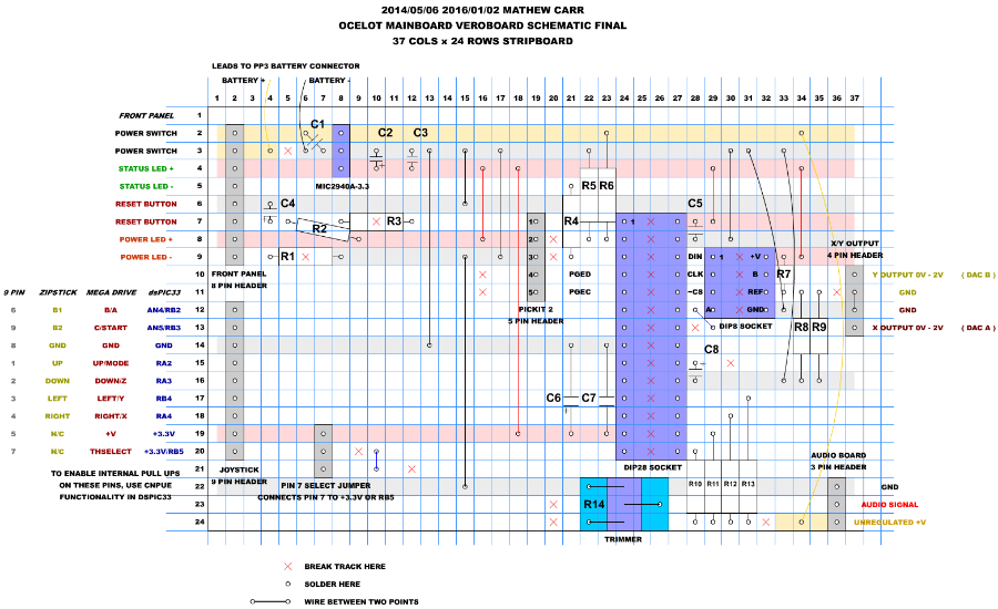
Click the diagram to expand.
37 columns by 24 rows stripboard
0.3 inch wide 0.1 pitch DIP 28 socket
Microchip dsPIC33FJ128GP802 16-bit Digital Signal Controller in 28 pin DIP package
0.3 inch wide 0.1 pitch DIP 8 socket
Texas Instruments TLV5618A Dual 12-Bit Voltage Output DAC in 8 pin DIP package
C5 - 0.1uF ceramic
C6 - 220uF low ESR electrolytic
C7 - 0.1uF ceramic
C8 - 10uF tantalum
Power switch
Reset switch
Power LED Red 2.0Vf
Status LED Green 1.9Vf
Micrel MIC2940A-3.3 1.2A Low-Dropout Voltage Regulator in 3 pin TO-220-3 package
PP3 connector (or other connector capable of holding a battery supplying 3.5V - 12V)
C1 - 0.1uF ceramic
C2 - 220uF low ESR electrolytic
C3 - 0.1uF ceramic
8 pin header for front panel
5 pin header for PICkit 2
C4 - 0.1uF electrolytic
R1 - 180R
R2 - 8k2
R3 - 270R
R4 - 220R
R5 - 10k
R6 - 22k
9 pin header for joystick
3 pin header for line select
4 pin header for analogue output
R7 - 240k
R8, R9 - 200k
R7 : (R8+R9) form a 1:3.4 voltage divider to shift 3.3V regulated voltage to 0.97V reference for DAC. Other values can be used if necessary to form the divider.
3 pin header for audio board connection
R10 - 240k
R11 - 220k
R12 - 200k
R13 - 180k
R14 - 50k skeleton trimmer pot
These values are chosen to provide a summing junction that combines the square wave signals from the audio pins at various intensities.

The power supply for the Ocelot mainboard uses a MIC2940A low dropout voltage regulator with pre filtering 0.1uF ceramic capacitor and post filtering 0.1uF ceramic and 220uF 63V low ESR electrolytic tank capacitors to provide a stable 3.3V for the dsPIC33 and TLV5618A ICs.
The leads of a PP3 (9V battery) clip are connected to the Ocelot mainboard to allow a 9V battery or a 3/4 AA battery holder to be connected. A USB power lead can also be used if the cable is modified to have a PP3 clip.
The unregulated power rail is kept available to power other peripherals. In the Ocelot, it is connected to the audio board to power the TBA820M amplifier IC. This chip can operate within 3V - 12V.
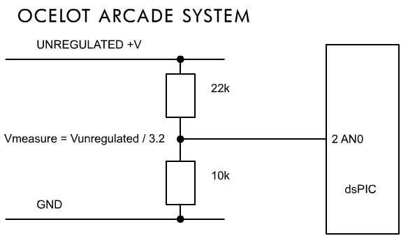
A 22k:10k voltage divider is used to route a scaled value of the supply voltage to pin 2 as AN0 analogue input on the dsPIC33 to allow the supply voltage to be measured. The Ocelot runtime blinks the Status LED on the front panel to indicate low power.
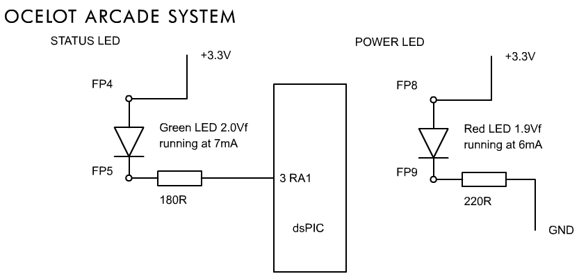
Two LEDs are mounted into the Ocelot front panel to indicate Power and Status. The Power LED is connected to the power rails, not the microcontroller. Ground of the Status LED is attached to pin 3 as RA1 on the dsPIC33 to allow software control.

A PICKit 2-compatible pin header is mounted on the Ocelot mainboard to allow in-circuit programming and debugging. Pins 1 as ~MCLR, 4 as PGED and 5 as PGEC are dedicated to PICKit 2 debugging and programming. The circuit above was based on the circuit from the PICKit 2 User Guide. The reset switch is debounced with a 0.1uF electrolytic capacitor. The 270R resistor protects the ~MCLR pin from static or capacitor discharge. The 8k2 resistor pulls the ~MCLR pin high when it is not pulled low by the ~MCLR pin from the PICKit 2 header or the reset switch.
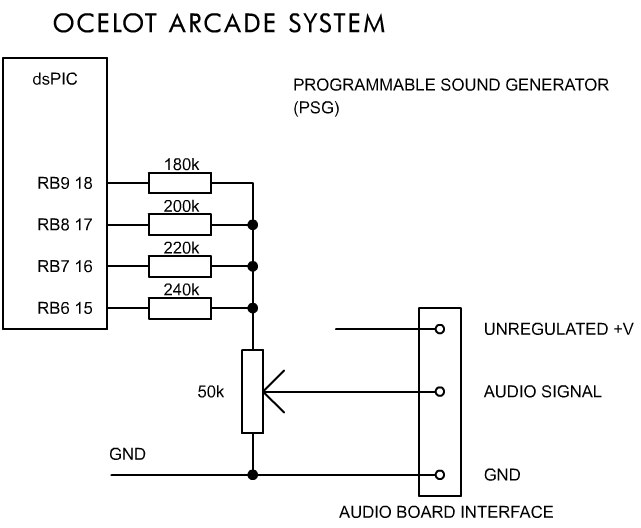
Pins 15-19 as RB6-9 are controlled as GPIO to create a four-channel polyphonic synthesizer. The output voltages of these pins are combined within a voltage divider network consisting of resistors to produce a single analogue value signal which is passed to the audio board. I conceptualised this as a summing junction of currents, with each pin contributing some linear amount to the final signal. A trimmer is used to adjust the final voltage to a suitable level for the audio interface.
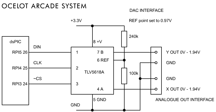
Remappable peripheral pins 24, 25 and 26 are configured to assume the roles of SPI channel 1: with 24 RPI3 as SS1, 25 RPI4 as SCK1 and 26 RPI5 as SDO1. These are connected to pins 1, 2 and 3 of the TLV5618A, forming a 3-wire one directional SPI bus. SPI channel 1 is used within the dsPIC33 to transmit a series of 16-bit instructions to the TLV5618A. Framed SPI mode is used to provide the correct framing required by the DAC. DMA channel 0 is used to feed data to the SPI on an empty event. DMA channel 1 is needed to constantly read data from the SPI symmetric channel to a dummy location. The display part of the runtime is smart enough to emit single channel change or simultaneous channel change instructions depending on the current cursor position within the buffer. A reference voltage of 0.97V is provided by a 240k/100k 2.4:1 voltage divider across the regulated +3.3V supply. The output voltages of the DAC will therefore be in the range 0V to 1.94V.
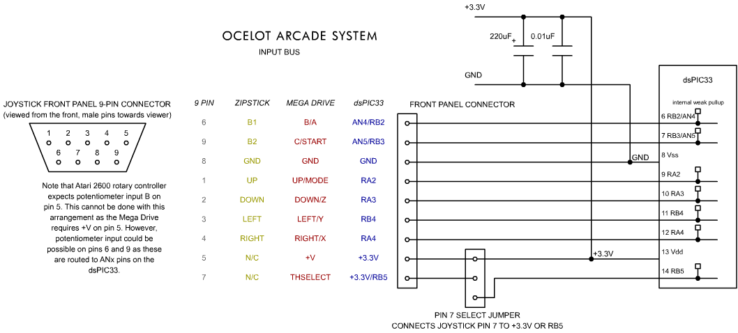
dsPIC33 pins 6 through 14 form the Ocelot input bus. These lines are connected to a 9 pin header which is connected via ribbon to the 9-pin JOYSTICK front panel connector (pins 1J through 9J).
Zipstick-style 1 and 2-button Amiga joysticks work by closing switches to ground when a button or direction is depressed. Five or six weakly pulled up lines are sent into the joystick. If a button is left idle, the switches are open and the line will remain high. If a button is depressed, the switch to ground is closed and the line will be pulled low. The dsPIC33 CN weak internal pullups are used for this purpose. The values of the general purpose port pins can then be read to determine current button state.
The Mega Drive pad is actively powered and contains a multiplexer chip. Pin 7J is used to switch between multiple pages of button states to read from the pad. (This is the same regardless of whether it is a 3 or 6-button pad.)
To allow Mega Drive pads to work, pin 5J is dedicated to +V supply. Pin 7J can be connected to pin 14 RB5 and driven by the Ocelot runtime to perform the necessary toggles.
A 3-pin header is installed between pin 7J and the dsPIC33 to allow pin 7J to be connected to either the +V supply or pin 14 RB5. This is to allow controllers that expect supply on pin 7J to work.
Ocelot board and case design, runtime software and Mattsteroids game © Mathew Carr 2014-2017. Starlynx game © Mathew Carr 2017. Ocelot 'Ask For The Future' © Mathew Carr 2017. Site design and content © Mathew Carr 2017.
All it does is provide a tinkering box with a solid 2-channel DAC. What were you expecting to see, I wonder? :)