Zero stops
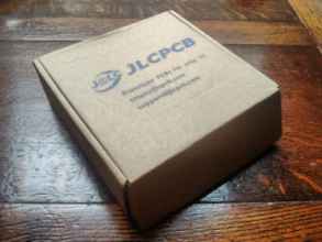
Hurrah! Thank you, JLCPCB!
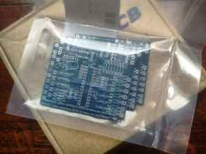
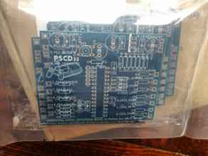
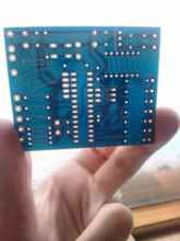
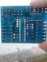
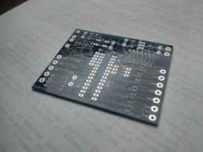
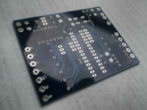
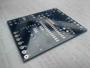
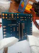
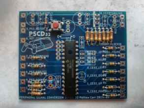
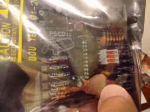
Five blue PCBs in a sealed bag! They look so amazing. I was expecting perhaps something a little sloppy and inexact, but these look flawless to me.
JLCPCB has a whole bunch of colours besides the standard Green. Green is faster, since I believe they panellise with other customers, and Green is the normal colour. If you pick a non-standard colour, you have to wait a couple of extra days for sufficient demand to cause a production run to be made (or so I understand). I got mine with no delay at all.
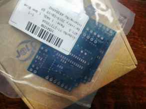
You should take a good look at your board for any obvious imperfections, and then do some tests with probes to make sure any routes you care to try are correct. For example, the power pins on the PIC should connect to the outputs of the regulator, ensuring the series of traces running over and under the pad are all present and intact.
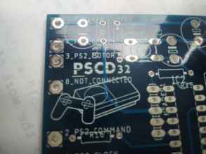
The vectorisation process in EAGLE's import-bmp converts the 1 bpp bitmap into a series of rectangular strips on the silkscreen layer. The PSCD32 logo has come out looking wonderful!
So shiny...!
These are brander than brand-new. I suppose they technically haven't even been manufactured yet...
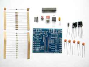
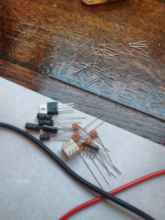
Here's the PSCD32 with all the components that need to be soldered onto the board.
• 1 * PIC24FJ32GA002-I/SP Microchip microcontroller DIP
• 1 * 5 pin 0.1 inch pin header
• 1 * 6mm tactile switch
• 1 * 3 circuit 0.1 inch DIP switch
• 1 * Micrel MIC2940A-3.3WT low dropout 3.3V voltage regulator
• 1 * 10uF tantalum capacitor
• 1 x 8k2 resistor (Grey Red Red)
• 9 x 18k resistor (Brown Grey Orange)
• 13 x 470R resistor (Yellow Purple Brown)
• 1 * 0.1uF eletrolytic capacitor
• 4 * 47uF electrolytic capacitor
• 5 * 0.1uF ceramic capacitor
Laying them all out and making a list lets you check them off you as you assemble the board, so you don't miss any out.
I'm using the PIC with the lower ROM size because... well... I dunno. I don't expect that my program will fill the 32Kbyte of the smaller one, so why not keep the larger one for Science... I mean spares.
Can you tell I took the original picture with the resistors the wrong way around and had the flip them horizontally in the image? :D
This is a resistor!
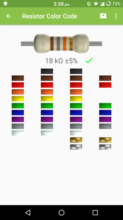
It's a good idea to test a couple of the components with a meter to see if they're what they say they are. Also, here's an Android app called ElectroDroid that I've been dying to fiddle with, and I finally have a reason to use it, yay!
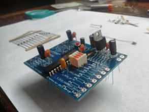
I'm going to slot most of the components into the board so I can see how it might look when it's assembled. It also more immediately lets you know if the footprints you've chosen for the drilled holes in the PCB match up to the real sizes of the components you intend to install. For example, the pins on the PIC were shipped slightly angled apart, not parallel. To put it into a socket or into this slot, I had to very carefully equally bend the rows of pins so that they were parallel before inserting it. This is best done against the desk, bending the entire row at once, with as little force as possible. The pins on the tactile switch were shaped like {} curly braces, ready to clip tightly into its socket. The pins on the header, regulator and DIP switch were shipped perfectly parallel, so there's no force holding them in place when inserted into the PCB.
The sizes of the components match their footprints perfectly, which is great! Double checking all the cryptic codes between EAGLE and tutorial sites really pays off. The one exception are the electrolytic capacitors. I chose capacitors with a 3mm pitch but a footprint with a 6mm pitch. The ceramics I chose are 6mm with parallel leads, as you can see in the laid-out image above, but the electrolytics' legs are narrower. To rectify that, I just carefully bent the wires outwards for a millimetre then bent them parallel at the right pitch so they would slide easily into their slots.
I'm going to have to be careful about the order I assemble this so I don't make it more difficult for myself then it has to be.
It's starting to look like a real zoo!
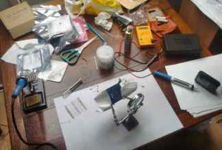
Here's my work area! It's a stinky old drop-leaf table, because that's what I've got.
• 25W Draper soldering iron. Almost certainly too cold for the kind of work I'm doing, and takes ages to heat up between joints, and the joints I do make look a little more matte than I expect as if they're cold joints, but they seem good enough.
• Paper laid down over the table to protect the finish from solder splats, debris and other mess. Also useful for making notes quickly.
• Tin/lead flux cored solder. I wonder if my iron is even hot enough to heat up unleaded solder?
• Solder sucker. Low tech. I've had rubbish luck with this thing when I've been modding existing device, but on fresh PCBs it works perfectly, especially if you have access to both sides of the board and lots of space.
• Lighter fluid.
• Cotton buds.
• Toothbrush. Necessary to clean up flux residue.
• Toolbox with pliers, wire cutters, small screwdrivers.
• Multimeter. Cheap, but functional. My one doesn't have a continuity beep, sadly.
• Lots of cameras.
• SAFETY PIN write about. asdadasd
I also have a desk lamp which I sometimes use for extra light, but it's more dazzling than useful. It's another thing to knock over accidentally. If you have a nifty huge workbench with a fitted overhead light, then go you.
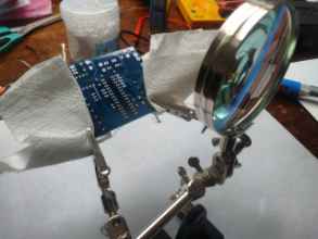
• Helping hands miniature magnifying clamp. This thing is phenomenally useful. Get one. Get two. Use kitchen roll over the jaws of the clamps to prevent any cosmetic damage to the board from the strong sharp teeth.
I don't use the magnifying part. In fact, for me it just gets in the way, and causes the handy stand to topple over frequently due to it being top-heavy, but I guess it can be useful at some points.
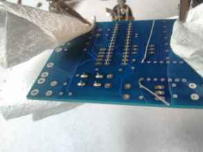
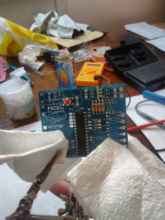
Inserting the tactile switch was a little difficult because of its crooked legs, and since taking it out would've been needless effort, I decided to solder it first.
Solder next to an open window, preferably during the day so you're awake and there's lots of natural light. (And no moths.) Never leave your soldering iron unattended, on or off. Make sure you have a sufficiently long lead - my soldering iron has a really short lead so I have to bring an extension over to the table. Use the little damp sponge on your soldering stand or station often to clean your bit. <blink>Safety is paramount.</blink>
Those joints look lovely, I reckon!
Use the continuity test mode on your multimeter to make sure the switch works and is fitted correctly. The switch itself is square, but the legs extend out laterally so it's rectangular underneath. If you've not forced it in and followed the footprint, it should be the correct orientation. Otherwise, you might have soldered it in as a permanent bridge between the two terminals! Test it before and after to make sure. :)
Next, the pull-up resistors to the upper right. When you're soldering resistors, always splay the leads underneath to hold it in place firmly. Loose resistors will have poor joints. When you're trimming the leads, use good pliers, and hold the end of the lead you're cutting firmly. You're applying a lot of energy into that wire, and it'll spring freely when it's cut. YOU DO NOT WANT THAT IN YOUR EYE.
I've inserted the PIC, but I'm not soldering it all at once. I've soldered legs in opposite corners to hold it in place first, but then swapping back and forth between resistors and the legs of the PIC so that it doesn't get over-hot. I really don't want to damage it without realising it and have to replace it. This is why we request spares when we request samples by the way!
I think I'm going to solder the components in order of their height from the board, then outwards from the centre so I don't have to reach over already-fitted things to put them in and work on them. First, the switch and the PIC because they're central, then the resistors, then the top row outwards.
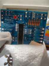
There we go. The resistors are all in. They're not as factory-aligned as I'd like, but they're solid and they're set.
Test them with resistance mode, and since they have a common terminal to the North, you can probe any pair of resistors to see if the correct 2X total resistance appears.
Tea break!
Remember to unplug your iron and keep the tea far away from the work.
Reset switch resistors, current-limiting resitors. Do it slowly, and gradually fix the PIC too. Everything's looking good!
You don't have to insert the resistors with the colour bands all in the same orientation, but it looks more professional by far. :D
The resistors and gizmos are next. Look at all those legs! A leg you collect is a leg you don't accidentally tread on later.
The 5-pin header is a difficult one to install. You don't have a lot of physical material to allow you to hold it in place. On top of that, the plastic collar between the long exposed pins and the short pins on the underside is very prone to melting. I melted part of the Ocelot's PICkit header because I held the soldering iron against the underside for too long.
The trick here is to find some connector that'll fit on the end (use something you don't mind possibly getting melted, don't use your nice working debugger cables!) and use that both as a heat-sink and as a handle to keep the component in place. I used a four-pin floppy drive molex power connector and lead I took from a parts bin PSU. It was the smallest, easiest thing I had to hand that had a 0.1-inch pitch. Just carefully attached the header onto the end of it, and use the helpy hands to hold the board and the component in place while I slowly soldered the underside. Like the PIC, it doesn't hurt to do it one pin at a time and give it time to cool down.
TALK ABOUT HOW TO INSTALL THINGS MORE
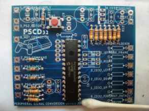
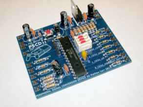
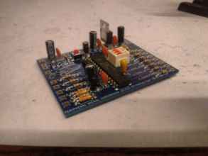
Wahey! Everything's done! It's a completed PSCD32! Dang, it looks professional. It might even work!
Except... the firmware of the chip is completely blank, so it won't do anything if you plug it in. And you can't plug it in because there's no interface leads soldered on yet.
But for now, it's time for bed. It's time for the PSCD32 to go to bed too; I'm giving it one of the huge anti-static bags that the components came in to keep it safe. Death by static would be a frustrating anti-climax.


