PSCD32 Development Diary

Constructing A Semi-Automatic Abstraction Around It

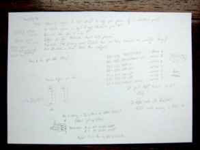
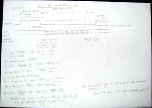
I'm going to adapt the previous implementation, but change the resolution of the timer I'm using. Instead of triggering on every possible protocol bit transition, I'm going to consider 'byte sending opportunity' units. In the Curious Inventor photograph, I can see some timing characteristics: • ATTENTION is pulled low first. • There's a delay before any transmissions take place. • CLOCK is pulsed and 0x01 is transmitted LSB first. • There's a delay before the next byte is sent. • The next byte is sent, nine bytes in total. • There's delay after the last byte. • COMMAND and ATTENTION are released. • There is potentially a delay before the next communication. If I consider the time span between two adjanced byte sending events as the 'byte sending opportunity frequency', I can develop a protocol that incorporates all the necessary delays like so: The vertical lines indicate timer events. When a poll request occurs: • ATTENTION is pulled low. Nothing else happens until the next timer event. • Bytes are sent on successive timer events until none are remaining. • On the SPI Transfer Complete Interrupt, store the received byte in the message abstraction structure but don't send the next byte until the timer fires again. • When the full message has been sent, a further timer event is used to idle. • ATTENTION goes high and a further set of timer events are used to stall before the next poll can take place. This is where the full message can be analysed. The timer resolution is set to be equal to the length of the SPI transmission = (8 + extra) * the SPI clock in cycles. The extra causes delays between successive byte transfers, and also accounts for the time wasted responding to the timer interrupt. The importance of doing this is in making sure the CPU is idle for as much time as possible. The way I'm modelling this in my head is to have the main thread of the CPU doing as little as possible, and all the interrupt sources performing the useful work. This way the main thread can run nothing but an endless loop of Doze state invokations, which means that whenever the CPU is serving an interrupt it'll process data at maximum speed, but when it's not it'll enter a low-power state where the necessary modules can still run at the correct speeds. (* it's not multithreaded, but it's as good a way to consider this as any) Let's do it!
A comedy of errors

main.c:491:4: warning: passing argument 1 of 'PS2_SPI_REQUEST_Timer1_SPI1_initialise_normal_request_loop' from incompatible pointer type main.c:260:6: note: expected 'struct PS2_SPI_REQUEST *' but argument is of type 'struct PS2_SPI_REQUEST *
Geez, I'm sorry! I defined a struct up at the top of the file that holds controller state, and then I copy pasted the struct later on so I could scroll up and refer to it easily. It was a temp thing, and I intended to remove it. I *think* it's a valid thing to leave in, if for some reason you couldn't remove it, as long as both versions are identical. BUT if you use typedef then you're setting an explicit renaming going on I think. So instead of the same definition of struct appearing twice redundantly, you've got two 'different' definitions fighting over the same name. And a function declared between the two will expect whichever one was immediately north of it. Variables declared will also take on the form of whatever one was directly north of it, so it seems like you can have two completely different types with the exact same name! So...
/* 'point' refers to this structure. */ typedef struct _point {int x,y;} point; void print_point(point *a) {printf("%d,%d",a->x, a->y);} /* 'point' refers to this -new- structure. */ typedef struct _point {int x,y;} point; void main() { point a; a.x = 10; a.y = 20; print_point(&a); }
I think that print_point() would blow up because it expects the first one but you're giving it the second one. The solution is to never typedef stuff twice because that's confusing and wrong. This is all because old style C doesn't allow you to define structures like C++ classes and Java classes, as just a list of members in advance you can refer to later. That way was added in relatively-modern C. In old C you're "supposed" to list the members of a struct at variable declaration time.
void main() { int count = 3; int foobar = 10; struct point {int x, y;} my_point; my_point.x = 10; my_point.y = 20; }
but I hate that stupid syntax. Because obviously you're going to want to refer to that structure type in multiple places, and different functions! The error is slightly more confusing in later versions of GCC it seems:
main.c:5:6: note: expected ‘point * {aka struct _point *}’ but argument is of type ‘point * {aka struct _point *}’
Even this doesn't work:
typedef struct _point {int x,y;} point; void print_point(point *a) {printf("%d,%d",a->x, a->y);} void main() { struct point {int x, y;} my_point; my_point.x = 10; my_point.y = 20; print_point(&my_point); }
main.c:5:6: note: expected ‘point * {aka struct _point *}’ but argument is of type ‘struct point *’
Anyway, that was a... aha... 'pointless' diversion. Back to writing SPI stuff.

SPI stands for Source of Puns Infinito

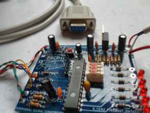
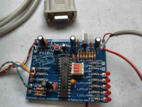
The masterplan is taking a little longer than I thought. I keep making mistakes, since my mind is halfway trapped between the old system where I'd be bit-banging individual bits, and the new system where I'm manually triggering single -byte- requests. The bytes in the exchange go from index 0 to index 8, and that confuses me even further, since that's the number of bits in a byte. On top of that, the SPI module can only transmit and receive MSB first. The Playstation hardware expects LSB first, so I have to manually flip everything I send and receive before it makes sense. For constants I could just compare and use them in their flipped form, but no. I've got a macro for flipping bits in messages I intent to send as they're stored in constant arrays. For real-time data, you can use a function or a 256-element look up table. And there it is! Directional pad and fire button reading is done! That means that this is an effective Zipstik simulator! Yeah! (Wait, one last think: when they light up it's because the MCU side is being pulled to ground... yes, that's right. When a physical button is closed, it shorts to ground. That's what my MCU is emulating. All is well. Also that bottom LED is Fire2, not Fire1...) So now I need to actually detect pad presence by considering the pad type number received, interpret the results from the pad, store pad state safely atomically so it can't be smushed mid-use, and then write the correct output for the CD32 in both modes - Dumb Two Button Atari, and CD32 smart shifting - and the transition between the two based on JOYMODE. Here's an observation on the hardware now that the PS2 side is nice and accelerated: The trace I've used to connect pin 26 on the PIC to pin 9 was necessary in my original design to allow ATTENTION to be provided by a RPx pin on the microcontroller. However, in my quantised system, this pin is now manually raised and lowered as a GPIO pin, not a SPI module controlled pin. This means it doesn't have to be an RPx pin after all, and the design would have worked equally well if I'd have put ATTENTION as an output from pin 9 on the microcontroller and left pin 26 unused. My software makes the ATTENTION signal output from pin 26 to match my original design, however, since that's how I designed it. A future revision of the PCB and PSCD32 firmware might fix this, but for now, it works, it works, it works. The next step is... splice the Amiga 9-pin cable in and remove my USB fake power supply bodge! --- put this expanation in somehwer?E?? Masked 2019-08-30 11:45:52 Best way to think of it is that the Timers and the SPI system are hardware acceleration. Masked 2019-08-30 11:46:18 They're asynchronous modules in the chip that you can enable to help you when repeating/timing stuff and sending things, which is exactly what I wanna do. Masked 2019-08-30 11:46:45 In my 'software rendering' version, I was using a timer to do every single clock wiggle myself, transferring things one bit at a time and manually altering all the voltages. Masked 2019-08-30 11:46:49 Which took up CPU time Masked 2019-08-30 11:47:06 The hardware acceleration approach frees up CPU time. Not *for* anything, just in general. Masked 2019-08-30 11:47:17 If I get round to doing proper sleep mode support for low power usage. --

Debodging?

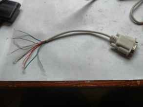
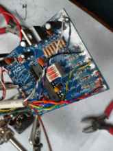
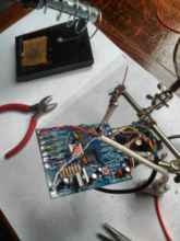
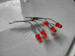
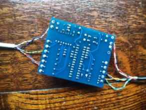
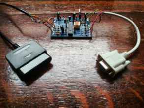
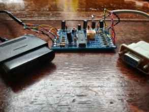
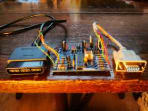
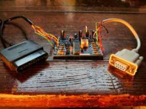
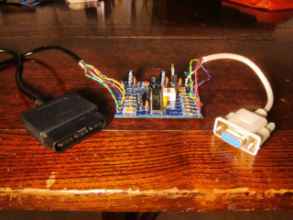
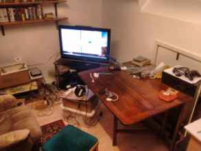
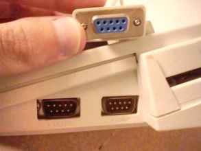
There's the end that has to go on this board. I've done pretty much everything I can do with these red LEDs. Gotta desolder them, same with the USB power kludge, even though they served me well! Blinking lights, we salute you. Thankfully, this is a true nine pin serial extension cable, so all the leads are present and correct. In fact, I even got a bonus lead in there for the shield of the connector, making ten in total. Got to test each pin in turn to figure out what lead is which once again. Draw lots of diagrams. There are LOTS of conflicting diagrams for 9-pin controllers. Despite what you may have heard, there is no standard. Do not take chances with your retro hardware. Assume that joysticks for different systems are incompatible and destructive. Wikipedia has (had? You never know with the deletionists.) a table of pinouts for home micros and consoles that have what appears to be a 9-pin interface. Triple check if you're making your own implementation of an interface. Most searches I did 'CD32 pinout' on Google Images returned an image that was totally incorrect! This is where a safety pin comes into its own! It's very narrow and pointed so it can slip easily into the female connector, and it has a large clip end and a coiled elbow for attaching or resting a probe. soldering cbalebslbsel The LED module has served me well. I can't bear to throw it away. It is, after all, brand new. Just need to remember it's common positive. I'm constantly terrified about the quality of my soldering. I'm used to seeing ugly mottled chunks on my work. But, a good PCB and good components, and everything looks lovely in this image. I think my soldering iron is just a little too cold though. Perhaps I'm just used to seeing my work on ancient tech rather than brand new tech. This is the final form factor(TM) of the assembled PSCD32 outside of whatever enclosure it ends up inside. The connectors are looking very lovely, even if they don't match in colour. I'm really pleased with how this came out! Here's a bit of cinema magic for you. I've made as much of a mess as I can here. Just have to plug this into the A600 and see what happens! Right. Yes. Didn't anticipate that. I was too used to the full-size ports on the Amiga 500 and 1200 which have the exposed screw lugs. Drat. I'm not too distraught about this. All it means is that I have to use one of my slightly-overused older computers rather than my rare A600 to test the device. That's probably definitely for the best.