The first problem was that I was writing to
PORTx and not
LATx.
What does that mean?
In the
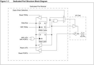
dsPIC33/PIC24 Family Reference Manual: I/O Ports with Peripheral Pin Select (PPS) chapter, you've got this diagram.
This guy indicates that:
• If you've set
TRISx for your port pin, it will be tristated.
• If you've set
ODx for your port pin, it will only ever be driven low, never high.
• When you read from
PORTx, you're reading the value from the I/O pin.
• When you read from
LATx, you're reading from the data latch.
• When you write to
PORTx or
LATx, you're writing to the data latch.
My problem was that I was writing to
PORTx in my code. In the manual it warns about doing this in assembly, but I was doing it in C, so it was even worse. When you manipulate the
PORTx bitfields in code, you read, mask, OR and write to
PORTx, which means you're writing a mixture of the values that you've calculated and want to send, and the voltage values present at the pin, which is rarely what you want. When folks say writes to
PORTx are the same as writes to
LATx, they're correct if you're only ever directly setting the value.
For some reason, that never came up as an issue with the Ocelot. I just assumed that setting
PORTx directly as well as reading from
PORTx resulted in tidier code. You learn something new every 2 A.M.!
The solution here is to be very, very explicit about what you're writing to. Triple check all your
TRISx and
LATx assignments.
This fixed some of the issues, but I can't quite get the second fire button working. Up, Down, Left, Right and Fire all work. I need Fire2 in order to get the CD32's serial protocol working.
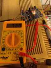
This time I think it's those 'squirrelly' pins. The resistor I installed is too resisty. When the PIC tries to pull it down, the Amiga is throwing so much juice at it that it only goes half way down and doesn't count as a zero. With a 470 Ohm safety resistor on the MCU side (expecting a max current of 12mA), it results in a 1.7V voltage at the output pin.
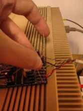
To determine the correct resistances, I'm using the very professional technique of simply holding a tangle of resistors with the leads twisted together against the exposed contacts on my board while the system is powered up. I think I ought to buy one of those resistors assortments in future.
Experimentally, by soldering towers of resistors that I had to hand, I found that the Amiga will respond to a pull to ground through no more than 70 Ohms. But let's do some maths.
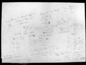
Using a few different values for the resistances and seeing what current was drawn through the grounded pin, I arrived at a model of the Amiga as being a 5V voltage source through 350 Ohms. Which means that to pull it down to 0.5V I'd need a resistor on the order of 40 Ohms.
Grounding without a resistor would result in a current draw of 17 mA, which is a heck of a lot of juice to just throw away detecting a button. It's pretty absurd considering the maximum current requirement for the PIC itself at 16 MIPS full number-crunching processing power is 20 mA.
I thought the maximum safe rating for a pin on my system was 12 mA. That is - if I told my mini CPU to Hold The Line unprotected, it would receive 17 mA flowing into that pin and it would die. However, re-checking the datasheet for the exact chip I have, it was 25 mA. Getting the good chips is always a good plan!
I *could* just connect it directly and let those ~20 mA fire all over the place; that's apparently what's happening every time you hold down a fire or mouse button. But I like safe things. I could have connected all the PS2 side directly too but it all seems happy enough as it is. It's safe, it's happy, I'm happy.
Adding a 40 Ohm resistor gives a current draw of 13 mA by the PIC when the pin is pulled low. That's not very 'digital logic', if I'm being honest. I'm not super jazzed about the idea but its safer than nothing. 5 Volts / 40 Ohms = 125 mA. That's a bit of heavy juice slopping out if things go awry and my model of the Amiga's pin is incorrect.
The direction switches are pulled up to 5V through 4.7k by the Amiga, so they're safe as houses.
There is a 4.7R resistor going into the joystick port's power supply which means that anything supremely slurpy is going to have some trouble slurping the system to death but from the amount of times I've written the word 'slurp' here, you might (correctly) guess that I don't want to rely on this.
