Back to Game Raccoon index...

Matt's Chronoblogical Misadventures In Game Raccoon Land Revision 1 - February - August 2020

Welcome back to Matt's Chronoblogical Misadventures In Game Raccoon Land! The date is 13th February 2020, and I've just finished putting the finishing touches on the Revision 0 misadventure page. I'm part way through laying out Revision 1 of the Game Raccoon. Let's see if we can make some sense of the madness.

Objectives

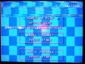
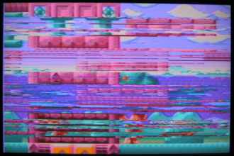
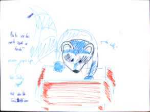
First, what do I need to change in Revision 1? Let's make a list of things that need to absolutely be changed and things that would be nice to change, organised in order of importance, except for the final item, which is critical. • Completely replace the control logic section - The cluster of gates in the lower centre of the board that detects the ROM reading and !TIME writing conditions is wrong. It's an intricately detailed, expertly manufactured mistake. I need to delete all the components there and go back to the drawing board. My starting information was wrong, so there's nothing at all that I can keep. I have to go right back to the cartridge edge and ask somebody who's done this before what the correct conditions are. The way around this would be to make a configurable board that I could alter to do experiments with... (That's not a pregnant ellipsis indicating that I'm about to do this, or know how to! It's more of a 'I'd like to know, but I don't...') • Fix FLASHREADY - The Flash module has a pin on the left side which indicates whether the Flash is currently idle and ready for a new operation, or if it is internally processing a length buffer write or erase operation. In Revision 0 this pin is connected to the PIC, but unfortunately I overlooked that the pin on the Flash is open-drain: i.e. the Flash can only ever pull it down and never up, as if it were a button switch to ground. The correct solution to this is to either add a pull-up resistor to the Flash pin to provide a default High state when the Flash is idle, or to connect the pin to one of the CN pins on the PIC which are capable of providing their own pull-up behaviour. On other PICs, such as the dsPIC33 series, there are many CN pins all over, but this PIC24 has much fewer than I expected, and as it happened I hadn't connected FLASHREADY to a CN pin. • Fix the reset button behaviour - This isn't critical. I've never had a Revision 0 fail to boot after pressing the reset button. This is a defect I'm willing to tolerate. • Fix the font loading shearing bug - I'm convinced this is a software fault in my rushed Revision 0 test menu due to my inexperience with the Mega Drive. I'll figure this out as I improve the menu and get more accustomed to the use of the VDP. If there was a hardware defect, it would affect all the games unpredictably. As it is, almost all software does have graphical faults, but they're predictable ones. If there was an intermittent fault, I wouldn't be able to leave Awesome Possum's title screen and attract sequence running on a loop and see the title screen and hear the fanfare perfectly every time they appeared. • New menu - The test menu is a bit atrocious, but it is functional! Programming a new menu is easy, but designing a new menu is a lot harder. Graphic design is not my passion, so coming up with a pretty menu isn't something that comes naturally or quickly to me. When the menu's in place, however, the Game Raccoon will really come alive as a concept. A great menu on an inferior device would sell it all by itself, for better or worse. But, alongside the new menu, there is something that I've been looking forward to figuring out: • The titular 'Game Raccoon' him or herself! - From when I came up with the name, I knew I wanted a mascot character on the title screen, and on the side, much like in the menu and battle scenes of Tetris Attack. I want a cute cartoon raccoon rummaging through an SD card-shaped box while the device is reading the SD card or installing a game. This means designing, drawing, colouring, animating, converting and programming him! • Allow the Mega Drive to read from the register - In Revision 0, the Mega Drive can only write to !TIME and not read from it. Any attempt to read from !TIME will return a floating bus. The only way for the PIC to communicate to the Mega Drive is through the values in the Flash module. This means that I'll be wasting one of the limited write cycles every time I want to communicate something. If I allowed the Mega Drive to read from the register through !TIME, then I could communicate bidirectionally - albeit awkwardly. This would allow me to report errors to the Mega Drive, not that there are any errors that are user-fixable while the Mega Drive is powered on: removing and replacing the SD card while the Game Raccoon is inserted into the cartridge slot is a very foolish idea. A bidirectional register would also make certain sequences a lot easier to implement: • Allow 'Game Raccoon Enhanced' games - At present, the Game Raccoon PIC's intelligent functions are only enabled while the Boot partition is active. There's no link between the two, it just happens that when I switch from Boot to Game, I disable the PIC to prevent it intefering in the non-Game-Raccoon-aware running game image. If I could detect whether a game was 'Game Raccoon aware', then I could choose to keep the PIC active for these games and allow them access to the PIC's functions, and, through it, the SD card and the Flash module. This would allow games to save and load to SD card, or to load new segments of themselves into the Flash in real time for games of potentially limitless size. This is pointless because there are no such games, but I could write one! Having the !TIME register bidirectional would help a lot for this. • Not break anything else - Apart from the VDP Blast Processing fault, the Game Raccoon Revision 0 works exactly as I envisaged it. I'm very proud of it, even if I am disappointed. I would really very much like to not ruin any of the edge connector, power, SD card, internal bus or register systems in my attempt to make the above changes.

What was good about the Game Raccoon Revision 0?

Let's quickly run through the things that worked on Revision 0: • The cartridge physically fit into the Mega Drive. It would've been a bit anticlimactic if it hadn't. I can't take credit for this - once again, I used Bruce Tomlin's footprint. • The board doesn't explode the Mega Drives it's plugged into. A small thing, but it helps a lot. • PCBWAY did a good job. You might have had a different experience, but I can't fault what I received at all. • All the components on the board are correctly powered and stable. I can't 100% attest to this: if this was the case, the Game Raccoon would boot perfectly without any fiddling of the Reset button. However, when it's on, it's on. The games don't crash or act weirdly. • The SD card library is working and reliable. Granted, I've only tested it with the first card I had to hand, but as long as there aren't any unexpected characters in the filenames or any malformed structures in the FAT, it works lovely. I wrote all those instructions in the Revision 0 Misadventure for anyone who wants to adapt the FatFs library for their own PIC projects. Since the only interface to the hardware is a small group of functions that exchange a single byte or a group of bytes with the SPI interface synchronously, the same instructions ought to apply to dsPIC33 devices too. • The transceiver logic was correct. It was wrong, but correct - when the 68000 asked for the contents of the mask ROM mapped to the cartridge region, the Game Raccoon Revision 0 replied correctly; the games booted and I got music and speech out of Awesome Possum. • The register logic was correct. Considering I'd never tried it before, and spent a month looking between two stacks of documents trying to figure out what the correct name for a component that stores 16 bits of data temporarily was (A latch, or a register? A legister. A flip-flop - but, ah, flip-flops make a register!), the register worked exactly as I intended it to. I'll talk a little bit more about this in the logic design section below. • The PIC, the Flash, the register and the transceiver all work together as a team. It's nice to assume that a bunch of 3.3V logic devices all working from a common supply will work together if you plop them all down and attach like to like, but there are a lot of very narrow connections all snaking around connecting these guys on the board, and a single design fault or incorrect assumption somewhere in the logic, or a routing or manufacturing error in the address or data buses would have prevented the PIC from programming the Flash properly, which would have prevented any game from ever working. • The menu worked. It's obviously very homemade, to put it lightly, but it displays the directory cache and lets you navigate it, and lets you select a game to be installed, and lets you boot it. When it's listed like that, the lack of working Blast Processing seems like the minor problem it really is. The terrifying challenge I have to surmount is to get Blast Processing working without causing any of the above qualities to change. How do I expect to be able to do that? By going very, very slowly. My Game Raccoon notes folder on my desk is a real slab of a thing now.

What's that streaky stuff on the pins?

This stuff? I'm not entirely sure. I don't think it's glue from the adhesive strip since I gave the edge a going over with lighter fluid after I removed the amber strip. I think perhaps it's solder, or some industrial mass-production equivalent? I'm not sure why it's there on the exposed pins. I thought they were supposed to be finished and plated - solid, hardwearing physical connection contact material. I don't recall seeing anything like it on the MegaBoard's pins (they were perfect), so I don't think it's a problem with the component I chose. I just don't know enough about it to evaluate it... the best thing to do would be to contact the man who made the Eagle component representing the board and see if he's any similar problems with it? For all I know this might be the standard plating for this kind of pin, and it's helping the contact with the edge connector a lot. It isn't preventing the boards from working. There's only one way down from that characteristic, so it's a problem for sometime else.

Let's see what's happening at PCBWAY!

My trust in and business at PCBWAY has earned me a loyalty perk. Avert your eyes, because you might not be ready for the power I now possess: And if I spend another £50,000 that goes up to 5%!? Gonna have to nail me to the chair. Well, it helps. :)

China is poorly.

2nd February: You may have heard on the news about the latest epidemic in China. :( So I'll be occupying myself with other things instead of working on Revision 1 right now.

Writing the Revision 0 Misadventure

What have I been doing instead of working on Revision 1? Why, working on the Misadventure page for Revision 0, of course! I'd love it if you read it, since it did take me ages, but I'd understand if you didn't...

Text in the header to identify Game Raccoon games

Up above I had a thought about 'Game Raccoon Enhanced' games being able to use the devices on the cartridge to do special things during gameplay. This concept relies on the PIC remaining active during gameplay instead of becoming idle. It's important that the PIC goes idle (i.e. not respond to register write events) during normal gameplay to prevent attempted !TIME writes by game images that are unaware of the Game Raccoon from having any (negative) effects. A 'Game Raccoon Enhanced' game would be the opposite: we'd assume that the game would only attempt valid operations upon !TIME, and, in order for the cartridge to respond, the PIC must be active and expecting the communication. One way to do this is to leave a specific message in one of the fields of the Mega Drive game header of the loaded game image to allow it to identify itself as a 'Game Raccoon Enhanced' game. My first thought was to use the 'device support' field, which uses characters to indicate what peripherals a game supports, such as joypads, modems, etc. I could define a character or string to represent 'Game Raccoon' (Revision 1), and detect the presence of the string when the 'boot current installed game' instruction is received by the PIC from the menu program. Looking through the Plutiedev docs, I am, of course, a few decades behind on the concept. :) The 'system type' field is already used for this purpose, with Krikzz' Everdrive series supporting special functions if the game identifies itself as being designed for SEGA EVERDRIVE or SEGA SSF (remembering that the SEGA characters are required to pass the TMSS check). I could use SEGA RACCOON or SEGA GAMERACCOON (if it fits - there are 16 bytes available) to identify my enhanced games. If I'm feeling particularly sneaky and smug, I could incorporate the required SEGA characters into some phrase of my own, like MOUSEGAMES, or, completely miraculously coincidentally and not at all intended: USEGAMERACCOON. (I was beaten to the punch on this a few years prior as well, ha. Here's Sega Retro's page on Funny World & Balloon Boy, released in 1993.) Of course * 2, this does mean I'm inventing my own standard that's completely independent of an established norm for which several games have already been designed, but I don't much care - the whole purpose of the Game Raccoon is for me to learn how to do things from nothingness. It would be very stupid to half-ass it if the board isn't fully capable of following someone else's protocol, which I'm certain the FPGA-less Game Raccoon concept can't do. Note that this header has to go on the games themselves, not the Game Raccoon boot image.

Respecifying the logic section

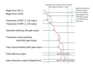
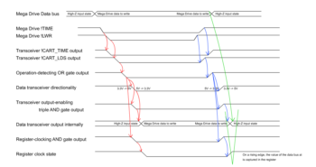
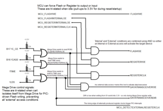
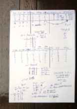
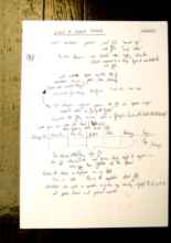
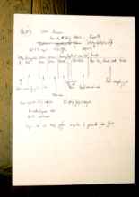
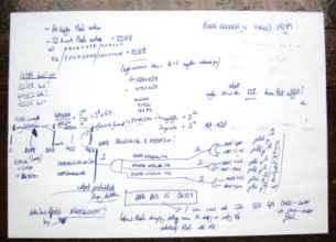
Let's begin with the real reason we're here. The cluster of gates in the lower centre of the board that detects the ROM reading and !TIME writing conditions is wrong. It's an intricately detailed, expertly manufactured mistake. I need to delete all the components there and go back to the drawing board. My starting information was wrong, so there's nothing at all that I can keep. Step one: fix the assumptions. My first assumption was that the Mega Drive as a composite device worked on the same signalling as a standard Motorola 68000 CPU alone. This was false. I went to SpritesMind and asked them what was what. Great kudos to user Sik for setting things straight very explicitly for me: • The B17 /CE_0 line should be treated as an active-low Chip Enable line for the cartridge region $000000-$3FFFFF. • The B31 /TIME line should be treated as an active-low Chip Enable line for the !TIME region $A13000-$A130FF. • The B16 /CAS0 line should be treated as an active-low read strobe. • The B28 /LWR and B29 /UWR lines should be treated as active-low write strobes. If one is asserted, a byte write is taking place. If both are asserted, a word write. With this knowledge, we can identify three external conditions that the Mega Drive can push towards the Game Raccoon: • A read from mask ROM. This occurs when B17 !CE_0 and B16 !CAS0 are both low. • A read from the register. This occurs when B31 !TIME and B16 !CAS0 are both low. • A write to the register. This occurs when B31 !TIME is low and either B28 !LWR or B29 !UWR are low. All writes to the Game Raccoon register ought to be word writes though. The fourth condition combination, a write to mask ROM, is ignored. Detecting these conditions to produce an active-low condition signal is done with an OR gate. • FLASH!EXTERNALOE = !CE_0 + !CAS0REGISTER!EXTERNALOE = !TIME + !CAS0REGISTEREXTERNALCLK = !TIME + (!LWR * !UWR) These are entirely different to the conditions detected by the Revision 0 board, so the control section is going to be completely different. Instead of passing B17 !CE, B18 !AS, B31 !TIME, B28 !LDS and B29 !UDS through the signals transceiver, I need to pass B17 !CE, B16 !OE, B31 !TIME and B28 !LDS. This means I need to erase and redraw all the wiring south of the transceivers on the board layout. I'd like the PIC to be able to perform all of these actions as well. Revision 0 can read from the Flash and read from the register, but I'd like to be able to write to the register as well. There's only one unused pin on the PIC, and it's in completely the wrong place for accessing the register. It's labelled as X12 in the schematic, and it's in the north-west of the PIC beside the PIC and LED indicator pins. There's no feasible way to include this new action without completely reassigning all the pins on the PIC. As well as moving the vacant pin to the south-east of the board where it can reach the control section, I need to decide what kind of signalling I want to use. To prevent poor PIC programming on my part from causing bus contention by accidentally having both the Flash and register outputting simultaneously, I could have a device selection pin that chooses either the Flash or register based on High or Low, and have a second pin for the output strobe signal. Alternatively, I could split all of the conditions out into single pins. It's something to think about. Time to draw it out and see what I can do. The simplest way to think about it is to consider it as three independent conditions that can each be independently overridden by the PIC with active-low signals. Each of the overrides is a GPIO pin on the MCU pulled up by default. The MCU still needs to detect register write activity triggered by the Mega Drive, so REGISTEREXTERNALCLK is still routed to the PIC. • FLASH!OE = FLASH!EXTERNALOE AND MCU!FLASHFORCEOEREGISTER!OE = REGISTER!EXTERNALOE AND MCU!REGISTERFORCEOEREGISTERCLK = REGISTEREXTERNALCLK AND MCUREGISTERINTERNALCLK It's deceptively simple. No, wait, that's a dumb cliché. What it is is actually simple. What's left are the conditions for the transceivers. The address and signals transceivers are unchanged: their directionality is always 5V -> 3.3V, never outputting from the cartridge onto the Mega Drive's address bus; and the enable is MCU!68000, allowing the Mega Drive's bus state to be reproduced inside the cart unless isolation is in effect. The data transceiver's conditions are vastly different to Revision 0, and it's very easy to get them wrong. • An external read from mask ROM. The cartridge should output a value to the Mega Drive. • An external read from the register. The cartridge should output a value to the Mega Drive. • An external write to the register. The cartridge should receive a value from the Mega Drive. In all other states, the data transceiver should be idle. This means that when any of the three external conditions are active, DATATRANSCEIVER!OE should be low. • DATATRANSCEIVER!OE = FLASH!EXTERNALOE AND REGISTER!EXTERNALOE AND REGISTEREXTERNALCLK The directionality condition is very similar to the Revision 0 condition. Here, the directionality should be 3.3V -> 5V always, except when an external register write is taking place. This means that DATATRANSCEIVERDIR should be High almost always, and Low only when REGISTEREXTERNALCLK is Low. Where the Revision 0 set the directionality of the data transceiver to the value of !W, Revision 1 sets the directionality to REGISTEREXTERNALCLK. • DATATRANSCEIVERDIR = REGISTEREXTERNALCLK There's one change I can make to simplify things that ought not to have any bad effects. Since the two byte write strobes are independent, and I know that any access to the Game Raccoon's register will always be word-sized, I can detect the register write by only monitoring one of the strobes. This means that if any software did a byte write to !TIME at the wrong even-ness of address, the Game Raccoon would ignore it. So don't do that. All of these individual stages add their own propogation delays to the service of the original request: These delays are also affected by the physical nature of the board they're realised on - capacitances and so on. The LVC logic ought to all work together super fine in close quarters like this, so I'm not going to add any special handling of these signals within the logic section. I don't know how long the Mega Drive (and being specific about this - not just the 68000 process, but the VDP as well and the composite system in its entirety) waits for a response before it whooshes off in search of new adventures. The typical ROM speed of a retail Mega Drive cartridge is 150ns I think, so as long as the sum of all the worst-case propagation delays incorporating the Flash's response time is less than this, then the Game Raccoon cartridge edge interface should be at least as responsive as a retail mask ROM cartridge. Writing to the register will be dicey, and I'll freely admit I don't know what I'm supposed to do about that. Writing to the register involves the same operation decode and IC activation sequence as a ROM read, but also has to correctly respond to the rising edge of B28 !LWR as well - when !LDS is raised, the register's clock has to be raised as quickly as possible too. There's two race conditions here: the data will vanish off the incoming Mega Drive data bus at some point after !LDS is raised and the sending of the write is completed. If this state occurs before the register's clock has raised, the state of the data bus will be indeterminate since nothing will be driving it from the Mega Drive side (except the the D0 pull-up for detecting isolation!). The other race condition is the digestion of the new logic state as the internal !CART_LDS rises, causing the on-board devices to become disabled: the data transceiver's directionality will revert to High 3.3V -> 5V output behaviour, and the data transceiver's output will be disabled. The rising of the final REGISTERCLK state occurs simultaneously with these events since they're all triggered by the rising REGISTEREXTERNALCLK external register write condition state. The 74LVC16374A 16-bit register has a typical negative hold time and a +1.5 ns worst case hold time, which I believe is faster than any of the other devices that would affect the state of the internal data bus. I'd like to introduce some way to ensure that the register clock occurred first, possibly by forcing the other logic decisions through another gate to introduce a delay, but I haven't done that. I suppose I'm relying on the capacitance of the internal data bus to hold the value for that 1ns (or typically negative time) that the register requires to capture the incoming value. Two important things to ensure are that the cartridge correctly responds to the limited set of conditions I've identified, and that it is correctly, completely idle in all other cases other than these conditions. Time for truth tables! There are sixteen combinations of !CE, !OE, !TIME and !LDS that can occur, and so there are a lot more output Lows in that table than there ought to be. There ought to only be three possible conditions that result in a Low, each corresponding to one of the conditions I'm specifically attempting to detect. What are the others? There are many rows that are 'impossible' according to the assumptions I'm making about the Mega Drive: !CE and !TIME should never be asserted together, since this would indicate an address in two non-overlapping regions simultaneously. !OE and !LDS should never be asserted together, since this would indicate a read and a write at the same time. Discounting these rows as 'impossible' conditions, the remaining rows are when only one signal is asserted, which indicates no condition I want to detect, or complete idleness. Also important is to specify which state these signals will be in when isolation is in effect. I want them all to be High, which means that they'll each need a pull-up resistor. Absent in Revision 1 is the direct MCU!68000 safety feature preventing the data transceiver from outputting in either direction during isolation. Since the data transceiver output enable is triggered by detected conditions based on post-transceiver external control signals, when the MCU!68000 isolation causes the signals transceiver to go into isolation, all these conditions will become impossible and the data transceiver will become idle. The only effect that the presence of this feature would have had on Revision 0 would be to isolate the internal data bus a logic gate propogation delay sooner. (Please don't bite me...) Now what on earth is that going to look like physically? The sets of three OR and AND gates should be combined into quad-input gates each. The 3-input AND gate at the bottom that combines all the conditions into the data transceiver enable signal could be a 3-input AND gate device if I can find one. This arrangement is conceptually pleasing in that each logic chip corresponds to a specific single function stage (detecting conditions, applying overrides, or detecting any condition requiring data transceiver action), with no loops or overlap. At the bottom of this diagram, you can see how many terminals REGISTERINTERNALCLK must connect to: • It emanates active-low from the output of an OR gate when !TIME and !LDS are both low. • It connects to the AND gate that ultimately produces REGISTERCLK. • It connects to the 3-input AND gate that controls DATATRANSCEIVER!OE. • It acts as DATATRANSCEIVERDIR - again connecting to two pins on the component. • It connects to the PIC as MCUDETECTREGISTEREXTERNALCLK. This is five different inputs for that one output. That's something that could become overlooked. (Oops - I didn't check the fanout of the LVC family before sending off to PCBWAY... I really hope that this doesn't come back to bite me. Hey! Wait! Why can't I find any information on fan-out in either Nexperia's or Texas Instruments' sheets? What am I missing?)

Redesigning the board: What needs to be done

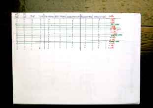
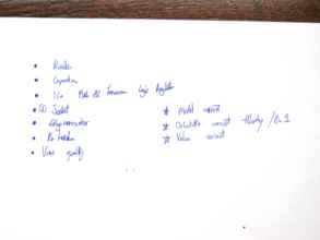
• Erase all address lines to PIC. • Detach all address line pin assignments. • Possibly move LED control lines and MCUFLASH!WE. • Add pull-up to FLASHREADY. • Move address routing in top-left of board to accomodate added pull-up. • Erase control section. • Erase signals bus allocation. <- No more !AS, !UDS. • Route !CE, !OE, !TIME, !LDS. • Add pull-ups for signals post-transceiver !CE, !OE, !TIME, LDS. • Flash IC !CE must be grounded. • Identify physical logic devices to use: quad 2-input OR, quad 2-input AND, single 3-input AND. • Get footprints. • Add to schematic. • Manually work out truth tables - all of them!! • Place footprints. • Route control section. • Step through theoretically. • Verify all address and data pins connect to all devices. • Constraint: MCUREGISTERDETECTCLK must be on CN/INT pin. Keeping it straightforward, there. Do it step by step, making tons of backups and taking lots of screenshots. If anything unpredictable or unusual happens, stop and draw it out on paper to make sure everything is fine. There's no room for error. Again. This took several solid days of work to work through. Erasing all that hard work wasn't a nice feeling, but if it doesn't work then it's worthless. Ditch it. I'm glad I had a lot of space in the top left corner to add the FLASHREADY pull-up. It's a shame I didn't think of it the first time - the datasheet ought to have made it more clear. Redrawing the entire address bus to reallocate the PIC pins was a long, tedious, laborious and error-prone process. Many sheets of paper were used doing checklists to ensure all the pins were linked to the correct destinations. The pre-transceiver signals needed to be redrawn, as I wrote earlier. The control section is phenomenally less complicated on Revision 1: the five separate devices have become three, each with their own specfic role. Seriously. I cannot overstate how important it is to review these truth tables and get independent verification that all your initial assumptions are valid. Applying new devices to the board means that there are new pinouts to learn. Don't ever assume that two quad 2-input devices that only differ in their logic function will have the same pinout! In this case the 74LVC08 AND and 74LVC32 OR do, though! Get the datasheets and refer to them constantly. Check the schematic symbol from your library matches with the datasheet diagrams. Check the package you expect the device to have, and measure the corresponding footprint on Eagle's layout screen. SSOP-* is not the same as TSSOP-*. Here's another ill-advised but therapeutic table showing the pin-assignments of one of the mid-edit states of the PIC. Drawing this table by hand lets you keep track of how many pins are used and whether or not you have all the signals you believe you have. The moment you write it down, you'll probably invalidate it with your next edit, when the realities of the routing stage conflict with the existing state.

Game Raccoon Revision 1 Checklist

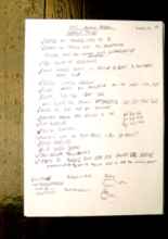
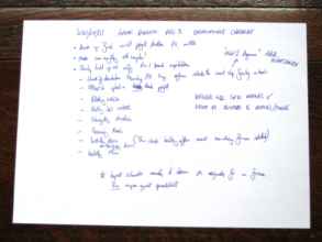
• Check logic requirements: what actions should be detected and how should they be responded to? • Check logic detection technique: truth tables, device connections. • Verify all device pin interfaces are as expected - signal polarity for enables, clocks, etc. • Design control section - what signals are being combined, to produce what? What pullups/downs do all signals need - anything that is open-drain, or tristatable. • Verify all control signals connect to correct pins on all devices. • Verify all address/data signals connect correct pins on all devices. • Check resistor values, part numbers. • Check all polarities. • Eagle airwire/error check with design tools. • Verify all pull-up resistors in place + correct roles. After finishing the board, it's time to sit back and enjoy the feeling of a job well d- No, actually, it's time to design the entire board again from first principles, just in case. If your answers here match up to the board you've made, then you're probably correct. Here, I'm listing every single connection and bus on the board that I can think of. The address and data buses, both pre- and post-transceiver. The generated conditions and what they connect to. The SD card. The Flash. The LED indicators. With that list, I can then manually check each pin on each device to ensure they all connect to the correct places on every device they're supposed to connect. Each pin on the data bus connects in five places: the Flash, the register (both input and output), the PIC and the data transceiver. Every possible location where there is a signal whose value may become indeterminate, a resistor should be placed to enforce a default value. This includes all the MCU GPIO control signals and all the post-transceiver control signals that can become floating during isolation. I'm not putting any resistors on the address or data buses: I'm not sure if I have to, but I didn't last time, and that was okay. Take a drink, if you're playing at home. Here's the pinouts for the logic devices once more. I'm paranoid about this. It would be very stupid to wire up the logic devices in such a way that was useless or, worse, dangerous (i.e. wiring two outputs together). Where's that checklist at? When all of that is done, it's time to:

Generate The Files

• Gerbers • BOM - export, python, reformat, Farnell numbers, verify manually. (I love that I went back and added 'need to verify all!' as an afterthought, thinking I'd forgot to add it; hence manually verifying my need to manually verify the parts list!) • PNP - export, python, reformat, verify manually • Orientation graphic • Price check Having manually selected, verified, measured, and prices all the Farnell parts, I've done pretty much everything there is left to do! I want to include a step-by-step process for generating the BOM and PNP files for PCBWAY in Misadventure 0, so it's probably a good idea for me to write down the process before I completely forget what it was I did...

Design Review Tools

I skipped over this on the Rev 0 Misadventure, so here's some more detail on Eagle's design review tools. The first one is a list of all the possible issues on the schematic. 'Only one pin on' means I've named a signal but I haven't used it for anything. This is good, since it means that I can correctly see that there are tons of signals coming from the edge connector that I'm not using for anything, like !AS at last. 'POWER pin on' is warning me about me connecting the power supply to the components. Depending on your footprints used, the pins may have included information indicating which pins are power and ground. You obviously want to connect these all of these pins to one of the supplies on the board, and if you have multiple voltages, you need to connect the correct one. Getting this wrong means that devices may be unpowered and the board completely useless, or, alternatively, the whole thing might just explode when you power it on. 'JP1 has no value' means... I'm not sure. I don't know what the Value of this component would be in Eagle. I'm using these two JPs for the PICKIT header and the auxiliary power supply. PCBWAY don't need to assemble anything here, so they don't appear in the BOM or PNP files I send to them. The second image is a list of the physical errors in the layout of the board (as opposed to the conceptual errors in the schematic). 'Dimension' means that there's a physical conflict on the board - something's been placed down on the board too close to an edge, or on top of where a hole would be. The tool lets you select each error in turn and focus the view on it. Almost all of these Dimension errors are related to the edge connector, which Eagle doesn't like being adjacent to the edge, but obviously that's intentional. I couldn't change it anyway, since the whole cartridge rectangle and connector are a single 'part' which I've placed onto the field from Bruce's library. Other Dimension errors are inside the SD card socket component: there are small mounting holes drilled underneath the footprint of the socket itself, but Eagle doesn't like how close they are to the solder points where the socket attaches to the board. There's nothing I can do about that. I know for certain it's fine, since Revision 0 was manufactured without issue and functions great. The 'Wire Stub's are errors in the laying out of wires - usually little tiny T shapes hidden behind larger objects. One common place where these appear is on the edge conectors at the bottom of the board, where Eagle's routing termination goes a little haywire (ha!) and doesn't make a clean landing into the connector pad.

The final images

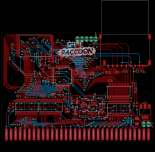
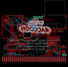
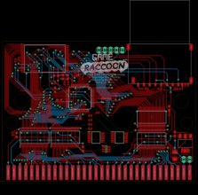
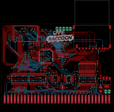
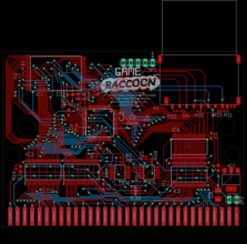
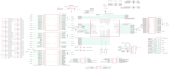
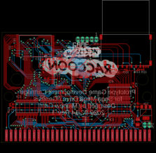
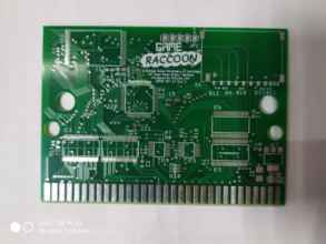
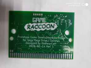
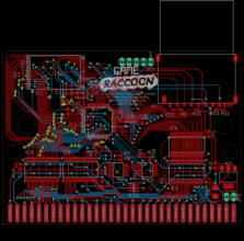
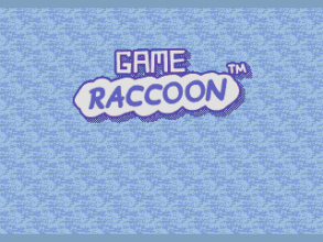
It's done! The FLASHREADY pin is pulled up. The logic section is completely changed. The parts are correctly Farnell-located, priced, footprinted, placed, linked up. I have hand-checked the new logic at least four times now... No funny text under the Game Raccoon logo... I couldn't think of anything. Plus it makes the first one special.

Files sent to PCBWAY

I sent the following files to PCBWAY: • GAMERACCOON_gerbers_2020-02-14.zip - Zip generated by Eagle containing the gerber layers and drill instructions. This is all the files needed to manufacture the unpopulated board. I don't include the BOM or PNP in my Gerber zip. • 20200214_BOM_gameraccoon.xls - BOM spreadsheet listing each unique component that needs to be bought to construct the final board. • For the centroid file, I sent a zip containing both 20200214_PNP_gameraccoon.xls and 20200214_gameraccoon_board_orientationguide.png. The PNP spreadsheet lists each individual component to be placed on the board with their position and orientation. The orientation guide image eliminates any ambiguity about component orientation, and the polarity of non-symmetrical components such as polarised capacitors and LEDs. "For SMT order, the lead time would be 30 days longer than usual. It would take more than 1 month for component procurement. Please refer to the reviewed quote for specific date." If I'm reading this correctly, the twenty day turnaround from Revision 0 has now become closer to sixty. Blast it. I've got no choice, let's do it.

I never learn

10th February: "and that's the story of how I learned to be more chill and multitask properly while waiting for long processes I have no control over to finish" *deftly twiddles quill around fingers and dunks it back into inkwell* 19th February: F5F5F5F5F5 audit the board already!!?!

Can I reuse the existing components somehow?

I e-mailed PCBWAY asking if they could take the Game Raccoon Revision 0 boards back and de-solder the components to use on the next revision, but was told that they couldn't do that due to the potential damage to the components, which is fair. I wouldn't want to do it myself either. Saving the cost of components would be nice, but introducing it as a potential confounding factor while I'm still prototyping the logic is not smart.

A different coloured PCB

Having each revision of the PCB a different colour would help me tell them apart! After checking though, a different coloured PCB for Revision 1 would cost a lot more than a standard green one, and that's before the effect of the virus epidemic. I'm afraid Revision 1's prototypes will have to be green.

APPROVED!

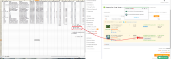
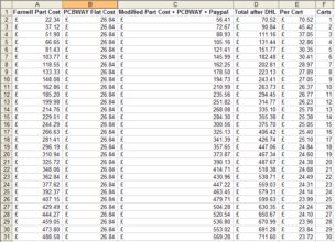
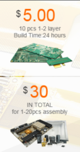
On the left is the spreadsheet I'm using to track the component costs of the Game Raccon Revision 1. It's a variation of the BOM I sent to PCBWAY. I've added a column for Farnell's price and minimum order size per component, and columns showing the number of each component required for 1, 2, and 5 boards, and the miniumum number of components needed to order to make that many boards. This value is the least multiple of the minimum order size that is at least the number of components required to make N boards. If you multiply that by the unit price (since I'm not ordering in 50+ multiples to trigger discounts) and sum for all the components, you get total component cost of N boards. The price on the PCBWAY invoice is greater than my estimation, which I attribute to shipping, management and profit margin. 'PCBWAY Flat Cost' refers to the PCB manufacturing and SMT assembly costs. I had to sort of fidget these in making the spreadsheet because I couldn't see them on the website... because I'm an idiot and didn't notice they were on the front page. There's a $5-7 PayPal charge they don't tell you about, which is a pain in the butt. PCBWAY currently have a 'winter sale' on, so the $28 DHL shipping is still free. This makes the only sliding costs for the quantities I need the component cost and DHL's multiplier. I've estimated DHL's costs at 25% of the total price paid, which gives me the values in the above spreadsheet. That's roughly the total price I paid for the five original Rev 0s. The total price Per Cart doesn't go below £22.40, which is the cost of components with all the cumulative percentage multiplier increases applied, with all the static costs disappearing to zero over infinite carts. Notice how the price per cart isn't monotonically* decreasing as the quantity increases. These steps are at multiples of 5 and 10 where a new 'box' of minor components must be opened to furnish the new boards. (* monotonic: a value changing in quantity, but never changing from increasing to decreasing or vice versa) Everything seems to be going well.

The final checks

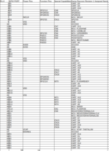
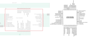
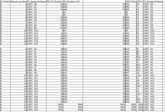
I've designed a spreadsheet that'll allow me to automatically generate the tables showing the GPIO pin assignments on the PIC for all the pins on the internal data and addresses. I've been doing this on paper up until now since I wanted to make any mistakes I was going to inevitably make slowly. The totals 53 and 11 at the bottom are the total GPIO-capable pins and reserved power/reset-dedicated pins. This table is a list of all the pins on the PIC I'm using, with their GPIO PORT pin assignments, reserved power pin assignments, interrupt triggering capabilities, and my Game Raccoon Revision 1 assigned role. These are copied from my Eagle schematic. In doing so, I noticed that the footprint I'm using in Eagle is incompletely labelled with the responsibilities of each pin. For example, there's no function indicators for the SPI1 channel on pins 33 and 34 here: I don't use SPI1, but it's a worrying omission. Always work from the datasheet directly! One very common mistake you can make with spreadsheets is to accept what you think you've typed as what you actually typed. Even if you didn't make a mistake, a modern spreadsheet application will recognise terms such as CART_A10 as labels, and will try to insert them automatically when you begin to type CAR... This means when you're typing many labels with a common stem, the label CART_A1 will be substituted for CART_A10 when you press Tab or Return, resulting in an error. This second table uses functions to extract the GPIO pin assignments for the internal address and data buses based on the above table: for CART_D0 - CART_D15, what are the resulting GPIOs I need to insert into my macros in the PIC main.c. I made this spreadsheet on the morning of February 20th, and it matches the tables I hand-wrote the week before, so I think that's it. I have made everything as sound as I can make it, and, once again, if I've got it wrong, I've got it thoroughly and comprehensively wrong.

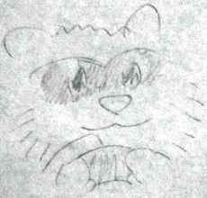
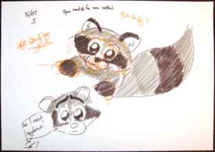
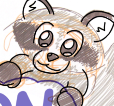
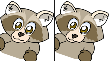
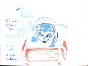
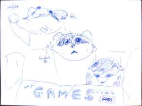
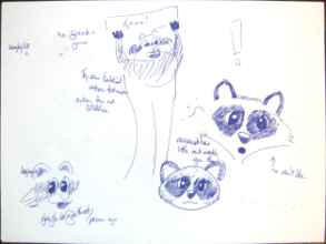
Mascot design notes

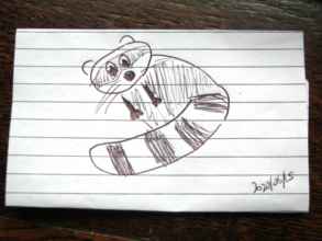
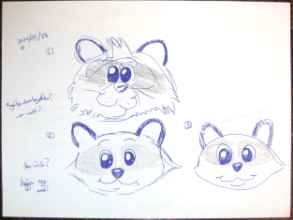
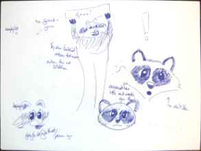
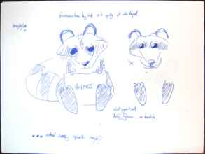
One useful thought is that the mascot illustrations have to fit (or at least look good in) the Mega Drive's limited palette, so I could work from there backwards. The Raccoon doesn't have to be grey, really... I could have a grey raccoon or a blue one or a red one or a pink one or a green one! Honestly, I'd like to get the Raccoon designed and animated by a professional artist. It would look awesome!

But what's this?

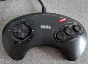
Someone ominously named Devilman has sent me a six-button Competition Pro Professional Control Pad Series III! (a.k.a. the SG-18 Series III by Honey Bee) This is going to be really useful for testing Mega Drive and Ocelot things with, since I didn't own one of my own until now. I'm confident in my rewritten six-button 68000 controller reading code, but the Ocelot needs some tweaking. (In a twist of fate, the Ocelot is a PIC acting as a console, reading a Sega controller with C code, so it'll be the same thing, but different.) Thank you very much, Devilman!

The new PIC firmware

For now, the PIC firmware is going to be almost identical to the one from Revision 0. I'm not going to introduce any of the new fancy features until Revision 1 is working at least as well as Revision 0 does. The first thing I'm going to do is: • Delete absolutely everything except the minimum code necessary to blink the indicators. The reason for this is that ALL of the GPIO assignments in the code will be incorrect. I need to go through each of the different devices on the board and enable them one by one in the safest possible way. If there's any contention, there's going to be damage. I have fewer extra lives this time, so the margin for error is smaller. When I get those LEDs blinking, I can enable the SD card, which should be unchanged from Revision 0 since its pins are preallocated on this PIC. When I can list its contents (through the debugger) and open a file correctly, I can move onto the Flash. Ultimately, the only changes I want to make from Revision 0 at this stage are: • Change the GPIO #defines to refer to the new GPIO pin assignments. • Change the Flash busy polling loop to check FLASHREADY instead. Only when the Game Raccoon menu firmware is complete, with the pretty menu and the mascot and the animations, should I worry about 'Game Raccoon Enhanced' games. I'm not going to mess with this until the PCBs are in front of me, though. Making changes to the software builds up a testing debt - I can make lots of changes before I have the opportunity to test them, and then try to test everything all at once, or I can wait until I can test the LEDs, verifying the board is stable and manufactured acceptably, then gradually advance. It makes sense to wait.

27th February 2020, Progress report

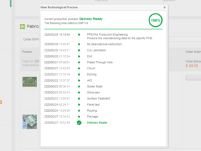
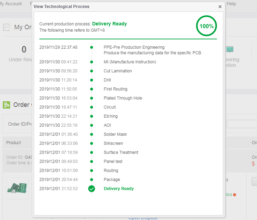
Alright, the assembly is complete. Now what? I feel like I ought to be doing something, but at the same time there's nothing that I should be doing. This interface is telling me facts, but not the right facts. If you compare this to the manufacturing progress table from Revision 0, we can see that PCBWAY sadly took three times as long this time.

6th March 2020, news from PCBWAY!

I think sending images of the bare boards and the preliminary component layout before mass production should be things a manufacturer does as a matter of course, but it seems like I'm always going to be chasing PCBWAY up about these myself. It's annoying. They could avoid this if they had a more descriptive interface post-ordering: I want to know ETAs on the PCB manufacturing after I place the order, on the components arriving, on the assembly beginning, on the assembly completing, on the delivery being dispatched, on the delivery entering the country, and when I can expect the delivery to be with me. These are pretty basic things. Also these photographs are pretty blurry - how am I supposed to evaluate the quality of the vias from these? The next stage is the assembly, which relies on the components arriving at PCBWAY. Where they are now, and whether they've been ordered at all is completely unknown to me.

What I can do with the remaining Revision 0 boards?

I ordered 5 Game Raccoon Revision 0 boards. I've permanently damaged one investigating my !AS-based logic, which leaves four. I haven't even cut open their sealed electrostatic bags yet. I'd have to solder on the PICKIT header pins for each cart and upload the PIC and Flash Revision 0 firmwares, and then I'll have four fully functional Game Raccoons that can do everything except DMA. * What can I do with these? (*There's a caveat about that) • I could play any homebrew games that don't use DMA. • I could see which games from Sega's download section on Steam do and don't require DMA, and for what. Monkeying around with games sounds like a fun distraction, but I believe the Exodus emulator has an option to lock any of the memory mapped registers (or bits of) to set values, which would (I think) allow you to view how games would behave if the DMA were inaccessible. • I could prototype the Game Raccoon Revision 1 menu, deliberately avoiding DMA use. This is the smarter option. Given that the only difference between 0 and 1 will (/should) be the DMA working (and FLASHREADY), there's no obstacle to making the menu. Revision 1 ought to have the same interface to the Game Raccoon's register (unless I decide to change it for some reason I don't yet know), so the 68000 menu firmware ought to be identical between versions. ---- Edit from the future, July 2020: Here's a thought experiment to do with nomenclature and assignment of quality adjectives. Let's assume the Revision 1 board works. That would be nice. That, conversely, means that the Revision 0 is something that doesn't work. What do you do with something that doesn't work, and may never work? You leave it alone and don't put it into your Mega Drive any more. Be smart, me. Leave it alone.

Cartridge shells, and a confession

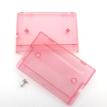
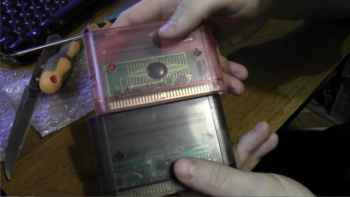
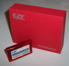
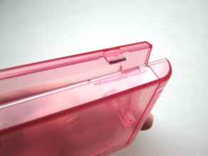
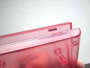
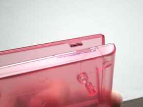
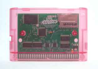
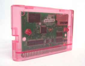
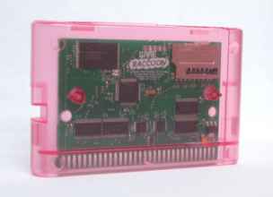
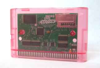
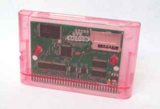
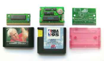
Since the Game Raccoon PCBs are so wonderful, it's time to put some serious thought to getting some cartridge cases/shells made for them. Way back in the distant past, I committed some pretty serious crimes against videogames. Back in 2012, when I first bought a soldering iron with the intent of making a Master System cartridge based on this blog post by little-scale (which later became the impetus for Gravity Beam: Master Gaiden) I all-but obliterated a spare Sonic the Hedgehog 2 cartridge in my quest to install a window into which a 28C256 EEPROM could be installed. At the time, I thought the world had way too many copies of Sonic 2 in it anyway. I hated that game... until I got good at it. After perhaps twenty-two years of trying, I finally got a Chaos Emerald for the first time in 8-bit Sonic 2 in late 2019, after repairing my Game Gears. I later won the game, and saved Tails! (I didn't win it on the Game Gear, that would have been Grade-A bonkers.). I did desolder the IC for Sonic 2 and keep it. I'm not a monster. They were strange, primitive, barbaric times, and I suppose all of my creative acts since then have been a sort of penance for this shameful display. A few months later, I bought a bunch of Genesis games I have no intention of ever playing. You can see where this is going can't you? Please understand this was in the era before cheap 3D printing. Well, strictly speaking, we're still in the era before cheap 3D printing, but this is before it was even plausible as a bad idea, never mind a good one. I bought that set for the Sega Nomad it came with (which later got sold to Ashens), and all but forgot about the games. When I was working on the MegaBoard, I had the inkling of an idea of mutilating Madden '95 or PGA Tour Golf to take a rectangular chunk out of the case to expose the pair of 28C256 EEPROMs along the top of the PCB: the MegaBoard was designed explicitly to allow installation in a case like this, since the thickness of the chips and sockets combined would not fit within the cartridge well of our Model 1 Mega Drive. We can definitely do better than this in 2020, can't we? I was going to ask the smart, cliquey folks on Twitter for advice, but I decided to try the blatantly obvious path first: AliExpress. I've bought a number of things from AliExpress in the past. I wouldn't rely on it for anything that has to have any kind of non-obvious attribute, and by that I mean anything that functions in any way. I've bought wooden rings and other wooden things from them and incorporated them into my Skull Kid costume, but I wouldn't buy, say... Any of these folks. These are like old friends now, huh? When you search for anything to do with the Genesis or Mega Drive on AliExpress, you'll get lots of these surely authentic and licensed cartridges of Sonic 3 and Crusader of Centy. I'd consult a professional before installing one of these in your console. For some reason, when you search for 'replacement genesis shell' on AliExpress, you will often get nothing at all. Which is pretty strange because there are tons of listings on AE for replacement cartridge shells: These guys look exactly like what I need! I wonder why there's so many of these being made. Of course, all those licensed cartridges would need a source of shells, I suppose. The best way to find these is to search on Google rather than AliExpress itself. I don't know why. All I can say is that AE's search is worse than useless because it's misleading. (N.B. not my photographs) They really do look the business. Though they only come in black, red, transparent black and transparent red. My choices would have been transparent colourless, transparent white or blue, but I'll take what I can get. I'm 99% certain that the Game Raccoon fits inside a regular Mega Drive cartridge, based on how it looked beside my Flashback cart and the good results I've had with Bruce's cartridge PCB footprints so far. I haven't taken apart one of the sports games to test yet. Just have to wait for these to arrive. I may die of old age first. :(

23rd March, A Challenge Appears

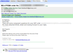
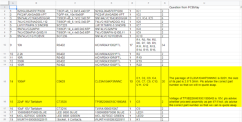
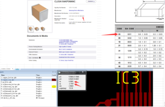
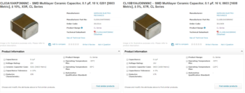
Something's gone wrong! o_o Oh no. In their spreadsheet, they've identified two errors. The standard surface mount ceramic capacitor which I've selected to accompany all the ICs is showing up as the wrong size! That's crazy, though... I copied the BOM from Revision 0 and that was manufactured just fine. So what's going on here? I opened up Eagle and started measuring the pads of all the capacitors, writing them down and calculating their size in millimetres. You know what I found? I'd selected the wrong capacitors and made a very understandable, probably common but embarrassing error. I'd mixed up metric and imperial measurements. I'd chosen CL03A104KP3NNNC, SMD Multilayer Ceramic Capacitor, 0.1 µF, 10 V, which is a 0603 Metric (0.6 mm x 0.3 mm) sized capacitor. The pads I'd placed, however, were 0603 Imperial (1.6 mm x 0.8 mm). The correct component I should have chosen was CL10B104JO8NNNC. I can only assume that PCBWAY silently switched my incorrectly specified capacitors before manufacturing Revision 0. Thanks! Though, that is really weird. I prefer being asked. The other error is saying that I chose the wrong tantalum capacitor for the regulator. I've written a value of 22uF 16V, but the TP3B226M010C1900AS is only 10V. I replaced it with the TAJB226K016RNJ. There's no voltage value given in the datasheet for the regulator that I can see, but I specified 16V to account for power-on spikes and the like. I haven't checked what tantalum capacitor PCBWAY soldered onto the Rev. 0 cartriges - it could be the 16V variant of the one I specified, or they could have used the one I selected. I should check. The Rev. 0 board that I've assembled does work though. I sent back an updated BOM 20200324_BOM_gameraccoon_revised.xls and manufacturing proceeded based on that. Thank you for checking with me, PCBWAY.

It's not looking good, everyone.

This virus is a real drag. I think when the Game Raccoon Revision 1 boards get here, I might need to get them checked by the party rogue for traps first. But I did get a $5 balance gift because I'm 'standing with PCBWayers'. I think? :o

30th March 2020, images

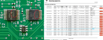
I got photographs! The Game Raccoon Revision 1 is looking fantastic; the new three-chip logic section is looking very smart indeed. My job is to make sure everything is laid out how I expect it to be: capacitors, resistors, SD card socket, ICs, edge connector, pin header holes and vias. As far as I can see, everything is dandy once again, and all the re-specified ceramic and tantalum capacitors are in place and accounted for. Hurrah! Now I have PCBWAY's own photographs of the in-manufacturing GR boards, I can compare the two: The vias on the Revision 0 look gigantic compared to those on the Revision 1. The 22P10 marking on the black tantalum capacitor in the lower right of the original Revision 0 indicates that PCBWAY installed the original 22uF 10V tantalum capacitor I indicated on the BOM. That's fine. It's what I asked for, and it works. The P in between the 22 and 10 is for 'high performance' according to the VISHAY datasheet. Comparing the two, you can see the data bus and SD card interface is completely unchanged between the two. The boards are the same colour in real life. I am a little concerned about the markings on the logic chips though. Let's have a closer look: On the right is the LVC08, which is a standard 7408 logic chip for the AND function. LVC is the family: it means 'low voltage CMOS', which is 3.3V, which is what my board runs on. The one on the right says LC32, which is a 7432 logic chip for the OR function. Why not LVC though? Have I made another mistake and selected an incompatible logic family in my haste? In the Texas Instruments datasheet for this chip, SN74LVC32APW, it says that the device will be marked with LC32A, which is fine. Similarly, for the chip below, the SN74LVC1G11DBVR 741G11 single three-input AND gate, C11F is the correct marking. Confusing, but there's a science to it, I'm sure. I have approved the design, so the other Revision 1 of that set will be shortly manufactured, and heck knows how long it'll be before it gets here. Meanwhile, the transparent cases have been completely dead silent since I ordered them a month ago. I sent them a kick-up-the-butt message and they replied with an apology and a 'Your Shipment Is On Its Way' e-mail. I checked the shipping information page, and it's still in some warehouse in China, so that's great.

1st April 2020, Manufacturing Complete

When PCBWAY gets going, they get going. The other Revision 1 one board is done. I wonder how long it'll take now... Revision 0 practically flew out of the building as soon as manufacturing was complete, but the current circumstances suggest that that might not be the case this time.

2nd April, Pay the Man

So there's a more informative breakdown of the import costs: if I'm reading this correctly, there's a £11 flat fee for handling (which is bullshit), and 20% VAT based on the listed value by the manufacturer, which seems in line with the amount I paid to have the boards made.

5th April, How unnerving

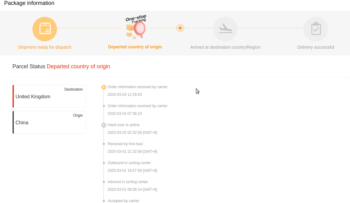
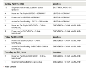
I think what this means is not that the box has gone missing, but that it hasn't yet arrived in the UK. It says UK because a UK terminal is adding the line to the report. The package is actually still in Germany though: since I paid the DHL processing and customs fee already, and Germany has checked it on behalf of the UK, the shipment should sail right in to UK with without it being checked twice when it changes countries. At least that's the theory.

Whooshier than a Wotsit

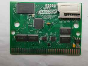
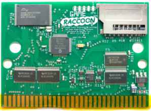
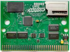
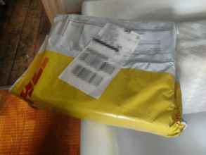
The original predicted delivery date was 14th April, but part way through the 6th the date changed and... Yep, the Game Raccoon Revision 1 boards are here! I can't read that, but I hope it says something like 'empty boards'. Let's see what's inside! More red bubble wrap! Above: Revision 1. Above: Revision 0. Above: Revision 1 unpopulated board. The assembly continues with aplomb. Got to clamp the board in the jaws - keeping it safely wrapped in kitchen roll - so I can solder on my USB cable to act as an auxiliary power supply for programming again. This is the same cable I used for Revision 0 since it snapped off with the stress of being used so frequently while I was testing the effect of grounding !AS. Also, I totally did not intend to get the five pin header lined up in the magnifying lens part of my helping hands in the first photo but that's an awesome turn of events and I love it! Time for testing: • The via in the lower centre is ground, as well as the one in the lower left. • The voltage incoming to the regulator should be 5V. • The voltage outgoing from the regulator should be 3.3V, which is found at the positive terminal of almost every capacitor, and pin 2 of the PICKIT header. • Pins 2 and 3 of the PICKIT header are +3.3V and GND respectively. • If the PIC-side terminals of the indicator LED resistors are connected to ground through an ammeter to simulate the PIC activating them, the blue LED shows 1.8 mA and the green LED shows 8 mA. Assembly complete. If you're wondering what kind of amazing soldering station I have, here's another look at my workspace. It's a stinky, knackered-old folding table in an attic with a cheap, possibly too-underpowered Draper soldering iron. Those nice pictures of the Game Raccoon board up there were taken with a Canon Powershot camera against white paper. Time to take this guy to the bigrig megacomputer, hook him up to the PICKIT and give him some brains.

2020/04/07 GAME RACCOON REV 1 DEVELOPMENT CHECKLIST

• Back up 'final' rev. 0 project directories: PIC, m68k • Make sure everything still compiles! • Slowly build up and verify Rev. 1 board capabilities • • Check if standalone Microchip PIC Image software ("PICKIT 2 Programmer") detects the correct chip family (PIC24FJ64GA006) on board. • • Attempt to upload a blank project. • • Blinking LEDs. • • Reading SD contents. • • Navigating directories. • • Accessing Flash. • • Installing ROM. (Then check booting after correct non-debug firmware installed.) • • Verifying ROM. • • Installing Menu. The objective is to establish the quality of the Revision 1 board as gradually and safely as possible. The differences in the pin assignments between Revision 0 and Revision 1 mean accidentally uploading the Revision 0 PIC firmware into the Revision 1 board will have dangerous and unpredictable effects, which absolutely must not be allowed to happen. The safest way to prevent this is to delete absolutely everything from the Game Raccoon project except the code necessary to blink the blue and green LEDs, leaving everything as idle, high-impedance inputs. Once the uploading process is established as working, then the installed capabilities of the Game Raccoon PCB can be introduced to the PIC one at a time. • Inspect schematic manually to discern pin assignments for .c firmware. Then compare against spreadsheet. To ensure that the old pin assignments are never accidentally used, I deleted them all and retyped them in based on inspecting the schematic again. Then when I've completed all my entries, I can compare them against the spreadsheet I prepared before ordering the board to make sure everything is consistent and valid. The SD card reading checks worked without any fuss. I'd forgotten how lovely the FAT library I'm using is! I can read and write files and scan the directory structure and everything. Next task is to get the Flash working. On the Revision 0 board, I'd made a mistake in attempting to use the Flash's READY/#BUSY pin by neglecting to give it a pull-up resistor, so I had to use the toggle pin polling method to detect when erase operations had completed. I believe I've correctly applied the resistor in Revision 1, so I can replace the polling loop with... another slightly faster polling loop checking the state of READY/#BUSY. I don't have to swap the data bus directionality from output to input every time I want to check the Flash readiness now, though, which might add up to a significant saving of time. Completely coincidentally, I've wired up READY/#BUSY to the INT0 function pin on the PIC, so I could use a rising edge interrupt to wake up the PIC from a low-power sleeping state if I chose!

The trying times of Game Raccoon Revision 1 Board A

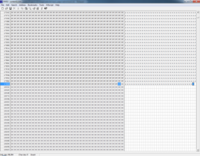
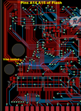
I tried to upload a 4 Megabyte image to the boot partition of the Flash, and... nope. I'm getting a light blinking sequence telling me that the verify operation failed: the Raccoon thinks it's written something to the Flash, but what's coming back out of it when I read it doesn't match the sequence that was just written. I'm glad I wrote that verification function now! I'm not glad that I now have to use MPLAB X's crazy, slippy debugger and the PICKIT 2's slow interface to figure out what's going wrong. It writes the first 16384 bytes correctly, but then fails immediately afterwards. When I'm looking at the retrieved bytes in the range 16000-17000, starting at address 16384 the bytes really are all messed up and garbageified. Instinctively, I can see that the bytes are coming out lower valued than they ought to, which is a familiar symptom which usually indicates that the Flash is writing over the same bytes twice: since the Flash programming sequence can only set a 1 to a 0, multiple exposures will result in more bits being set to 0 than there ought to be. Why this is happening is a mystery. My first thought is perhaps the Flash module is defective or counterfeit, and I'd somehow been writing over the same block when I was linearly scanning through the address space. First things first though: making absolutely certain that every single one of the fifty-one pin assignments and multiple C #defines for each pin were consistent and correct. Yeah, they're correct. Super correct. Alright. Next, check that FLASHREADY isn't messing anything up. This is a new feature for Revision 1 and it's possible I've specified the wrong kind of resistor in the wrong way, but I'm pretty sure it's fine. I'm busy waiting on the signal rather than using an interrupt for simplicity. If I'd wired this up wrong, I don't believe I'd be seeing the correct delay when erasing a sector. I can return to the timing-based wait if I need to. Just in case I've messed up the FAT of the SD card by using FatFs incorrectly, I'm going to yank it out and reformat it and try again from scratch. I test wrote 256 bytes from 0x00 to 0xFF to the first 256 of the Flash space and then dumped the Flash memory contents. The values were mirrored at address 16384! It was if the Flash module was only 16384 bytes big. I decided to format the entire Flash and then read it back, and I got a very strange striped pattern of blank Flash with large blocks of zeroes every 0x20000 from 0x18000 to 0x20000. Something is very wrong with this board. All the data lines are fine, since I can write and read any value correctly as long as it's within the first 16384 bytes. Seeing strange patterns repeating within the address space reminds me of the apparent mirroring behaviour of mask ROMs when they're accessed at addresses beyond their address space: what I think is happening is that one or more of the address lines is stuck low, high or to another address pin. And with some thorough poking and prodding, there we have it. You can't see it very clearly here, but I'm touching the probes to the vias that connect CART_A15 (on the left) and CART_A14 on the right. These pins definitely shouldn't be showing a zero resistance, but they are. Let me think about what the consequences of this could be... well, they're always going to be driven together by either the transceiver or the PIC. The transceiver should be in isolation for now, so it's just the PIC driving it. The risky zone is whenever the values of A14 and A15 are not equal, which happens in the address range 0b0100 0000 0000 0000-0b1011 1111 1111 1111, which is 0x4000-0xBFFF, or 16384-49151, repeated every 65536. Any access within this range will result in an indeterminate value at the address pins due to contention, and the PIC shorting two of its pins together in a dangerous dave display that will likely destroy the universe. I'm going to have to test every single possible pair of signals for the correct resistance value. Lovely. That narrows that down then. My poor hands. CART_A15 and CART_A14 are pins 1 and 2 in the top left of the Flash module. I can't see any solder bridging here, but if there were any, this is where it would be. The third photograph is showing the immediate north of the address transceivers: the via on the trace running through the number 3 is CART_A14 and the one immediately to its left running through the tips of the C is CART_A15. There's some solder-looking debris here, but it doesn't look like it's making contact with anything. The lines also are parallel where CART_A15 uses a via to go to the top layer of the board to connect to the leftmost pin on the bottom row of the PIC. I can't see any damage or manufacturing errors though, but clearly something is physically, dangerously wrong, and this copy of the Game Raccoon Revision 1 board is completely useless and cannot be used. Let's call it Board A. I am very, very glad I bought two!! Never buy just one prototype board!!

You can't spell 'refund' without 'fun'

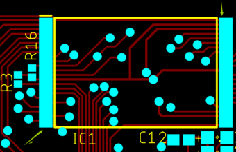
I've skipped ahead a little here in time, but I want all this first board stuff together in this post, so if you're more interested in what happens with the second prototype board, please stand by! I've made a decision. I'm going to ask for a refund or a replacement for this one board that doesn't work. There's absolutely, definitively a short between A14 and A15, making it useless for me. I can't see anything obviously wrong with it, no great big solder blobs or debris. The second Revision 1 board works just fine, so there's no reason why the first board should be any different, so it's up to them to fix it. I paid my money, and I'm going to take my choice. Two boards, thanks. First up, PCBWAY want to see a picture or video of the short circuit, and whether it was caused by soldering or the PCB production. I can't see any physical mistakes in the making of the board; it looks just like the others from the set, so it has to be either the soldering or defective parts. They're going to be pretty dull pictures. Here's a cultural note that you might find useful - among the many, many, many sites that are blocked by the China firewall, you'll find Imgur is one of them. So don't attempt to send a gallery of images through Imgur instead of an e-mail attachment. Gee, sure hope I didn't get anyone into trouble. In response, PCBWAY sent me the above image showing the layout of the solder mask around the Flash IC, IC1. The areas of light blue show where solder is exposed on the board. The circles are the vias, the squares are the resistor and LED pads, and the large rectangles cover the entire pin area either side of the Flash IC. PCBWAY says that I ought not to have indicated an unbroken rectangle of solder mask here, and that is a possible cause of the short. I'm a little confused about that - I assumed that this was the normal layout of solder mask, since it was the default that popped out of componentsearchengine.com's library for this component. Making that area more fiddly by separating out each individual pin sounds a bit strange and I wouldn't want to make any overambitious assumptions about the resolution of the manufacturer's process by altering it from the component default. I also contacted the EEVBlog forums for advice and they suggested retouching the solder along the left edge of the Flash or removing the chip entirely to look for a board defect. I'm not really comfortable doing either of these things - it feels like buying a new car and then being asked to open the hood and start unscrewing things yourself. It's unanimous that I ought to just dive in, so let's see what trouble we can get ourselves into. One respondent suggested that there could be a ridiculously fine short between the two pins that could be split apart with a blade, so I started there. I've been as gentle as I could possibly be, and I've made a mark, but the fault remains. Nuts. There's no visible mess, faults or strangeness anywhere else on the board. A14 and A15 aren't colliding with the power rails at the top edge of the transceiver and don't mingle anywhere else; they even connect to the lower edge of the PIC on opposite sides. I'll take any excuse to take some gratuitous macro shots of the board though. Somebody suggested I inspect the back where the vias and the traces are closest, but there's nothing unusual there. I've washed them plenty of times. Take a look at how misaligned the solder mask is with the vias, by the way. If I'd somehow altered the solder mask to isolate each pin as suggested by PCBWAY, what are the chances that the solder mask would even end up correctly exposing each of the tiny pins? I received a mind-boggling response from PCBWAY when I sent more pictures and told them about my testing: "Thanks for your pictures, for the picture of IC1, it seemed no clear short circuit of the conecting pins by soldering. For your repairing, what do you plan to do?" What do I plan to do? I plan to e-mail you and ask for a replacement for the thing you made which is defective. What on earth kind of question is that? Seriously, though. It's time for me to ante up and finally buy myself... a flux pen! Figure 1: one (1) flux pen. A flux pen is a pen that contains flux. Flux removes oxides during soldering, and improves the resulting quality of connection. I use standard 60/40 Tin/Lead solder with a flux core for my soldering. For surface mount work at home, whether it's soldering or reflowing, a flux pen is necessary. So is desoldering braid, but I've ran out of that after the PSCD32. So what exactly am I going to do? I'm going to follow this guide - https://www.youtube.com/watch?v=PUFCDh9BxQU - and attempt to reflow the solder connections on the left side of the Flash IC. Hopefully without dislodging or destroying the resistors running down the left hand side, or mishandling the board. Here's the plan: • Clean the soldering iron tip on a sponge to remove as much solder as I can from it. • Apply a line of flux to cover the area where the IC pins are. • Slowly draw the iron across the Flash IC. I don't know what direction would be best - I ended up doing it right to left with the pins facing towards me, due to my left-handedness and the way I had the work laid out. • Remove any excess solder balls with braid (which I don't have), so I'm going to use the pneumatic solder sucker instead. This might be really bad or it might be really good. Who knows! • Clean up the flux with lighter fluid. I have a brush for this, but I also use cotton buds. The objective is to reflow the solder on all the connections on that side of the Flash IC as well as gather up and remove any loose shards of solder or flux that aren't visible to my eyes. The end result should be a series of perfectly neat, secure and correct low-resistance solder connections. I will be able to tell I've done it right if there's no visible bridges between any of the pins and all the adjacent pins show the correct resistances when I use the probes against their vias again. Yep, gotta do that spreadsheet a second time. And then I have to solder on a new programming pin header which I destroyed and reattach the auxiliary power supply... AND IT WORKS! It's magic! Two completed Game Raccoon Revision 1 boards, ready for Adventures in Research and Development. In the end, I didn't get my refund, but I did get some store credit to make up for them messing me around. You wouldn't believe the amount of fuss I went through to take this photo: the grey cable kept wanting to fly out of my hand and flip around like mad. I had to grow a third hand to hold it steady. I have no idea what these two cables used to be before I chopped them up. Almost certainly something completely useless or bizarre, but not rare. But what did I do while I was waiting for PCBWAY's response, and the flux pen?

Back in Time to Board B

We're back a few weeks before the flux pen arrived, I've put the malfunctioning Board A to one side and I'm going to assemble and use Board B for now. There's no difference between the two boards, they're just the two factory-assembled Revision 1 boards that I have. Alright! That's what I expected to see. I'm testing A14 and A15 on resistance mode, and they're entirely independent, as they should be. Doesn't rule out another defect elsewhere in the board though, but I'm going to put this in the programmer and get it going. First, I need to snip the power supply off Board A and attach it to Board B, and then solder on a new programming header. I can't take it off Board A, as these tiny little things have a habit of melting when you just breathe on them. Looking through my box of electronic knick-knacks, and I've found the last bit of the pin header strip I've been using on the Ocelot and friends... Blast. I kind of need a five-pin header to connect the Raccoon to the PICKIT! Hmm. I looked through the bits I have for the PSCD32, and found some more five-pin headers from that project. Yay!! :D This is why you should always buy 250% of everything: you get lots of attempts to make one, you can make two if you're lucky, and if you design your projects using recurring parts and techniques you can pass the spares between them. Note to self: buy more 0.1 inch pin header strips!

With Board B assembled, it's time to stick it in the PICKIT

Didn't work. Not a thing. I booted up the PICKIT 2 Programmer program, and it couldn't detect the board at all. Fabulous-mazing. The PICKIT 2 is working fine, since it was programming the PIC in Board A without any issues, but, attached to Board B, it's acting as if there's no PIC there at all. Is the PIC itself broken? Did the PICKIT 2 explode inside from having to deal with Board A's nonsense? Is this board defective too? This is as good a time as any to make a semi-apology for something I think I might have been vague about in my previous post.

A semi-apology for something I think I might have been vague about in my previous post

I wrote: • "PCBWAY did a good job. You might have had a different experience, but I can't fault what I received at all." It's time to add the inevitable caveats and qualifiers to that statement. The Revision 0 boards all visibly appear fine; I ordered five PCBs all assembled, but I've only soldered on header pins and a power supply and programmed one of them. I have absolutely no idea whether the remaining four assembled Revision 0 Game Raccoon boards work at all. I don't want to make it sound like I had a 100% success rate. I had a 20% success rate and 80% maybes. When I get more pin-headers, I could finish off the Revision 0s by giving them menu and PIC firmware and maybe give them away to anyone who wants to develop DMA-incompatible Mega Drive software, but I lost interest in them mostly after them not being up to the standard I set myself. As for both Board A and Board B Revision 1 boards not working, I think I'm going to have to sleep on it.

{ ~ matt sleeps on it ~ }

First things first, go back a step and try again. I took Board B upstairs and washed it with lighter fluid, washing up liquid, and an antiseptic wipe. Then I reflowed all the debugging interface pin header connections and the power supply. Made sure as best I could that the holes were filled properly and everything was secure. Retested all the voltages and LEDs again. Then washed it and tested it again. And, putting it back in the PICKIT... No faults, no errors, no weirdness. It's being detected by the PICKIT software as it should be. I wrote 4 Megabytes to the Flash just fine. I can write the directory record cache to the Flash and then read it back out to the SD card as a binary file. Everything looks good! Nothing left to do but try it in the Mega Drive! Just how good looking is the silkscreened Game Raccoon on the back of the PCB there? :D It pokes out perfectly above the slot of the Model 1, and I didn't even measure it or anything...

Kicking Butt Like A Champ

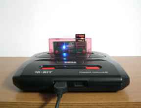
I tested the dump of Awesome Possum Kicks Dr. Machino's Butt in the boot parititon of Board B as per usual testing protocol, and everything is grand! I'm seeing Awesome, the scenery, the text, the quiz animals, hearing the music, the fanfare and Awesome's speech. Everything is, well, Awesome. Hurrah for Awesome and his fanfare of justice! Time to install the 68000 menu firmware into the boot partition and see if this thing truly is a complete Game Raccoon. I don't have to modify the 68000 menu firmware for Revision 1. The only coupling between the board design and menu firmware software is in the interface defined for communicating across !TIME through the register and into the PIC. Since I haven't changed this protocol from Revision 0, and the register is still logically routed to !TIME with the new control logic, the menu firmware's routines should work without modification. GO! Alright! The Tanglewood demo works and is looking fantastic! I've played the demo from beginning to end, with absolutely no problems. One cute little colour-changing foxo working flawlessly on real hardware on a CRT, as it should be. n.b. This project is not associated with Big Evil Corporation. That's it. There's nothing more to do! The Game Raccoon is complete! Well, not quite. Let's thoroughly make sure the DMA works for one thing.

Let's try some more games!

Things that work: Wiz 'n' Liz: The Frantic Wabbit Wescue by Raising Hell Software. Zero Tolerance and Beyond Zero Tolerance by Technopop. These retail images from the developers work wonderfully! I'd have been surprised if they didn't since the software has been fully tested to work on Mega Drives and my cartridge imitates a standard cartridge as close as it possibly can. I'd never heard of the game Red Zone before working on the Game Raccoon, so I have no idea how I managed to get my hands on HardWired (Prototype), a freely released prototype of what would later become Red Zone, but it works amazingly too! Rotating polygon islands, 3D interiors, 1-bit smooth silhouette FMV intro, the works. Tanglewood (Demo) by Big Evil Corporation. UWOL: The Quest for Money by Shiru & The Mojon Twins - Mega Drive link UWOL's a lovely game, still. A lot of fun for less than 64 kilobytes! (The only reason I know of UWOL is that I wanted to find a homebrew game that was small enough to fit in the MegaBoard's twin 28C256s.) If I remember, UWOL worked on the Revision 0 board, so it's reassuring that it still works, and that the Game Raccoon doesn't go funny trying to write really small images. Misplaced by RetroSouls Misplaced is a lovely, pretty puzzle game by RetroSouls, a Mega Drive developer that releases a lot of their games on itch.io. Misplaced works great, though there seems to be a row of tiles that have been mis...located from the banner on the end screen. Sadly none of the other RetroSouls games such as Old Towers or Yazzie work at all! (At the time of writing this page (15th May), a fourth RetroSouls game has just came out: GLUF! It also doesn't work...) I suspect most of the things that don't work are NTSC only. Or they just weren't tested on hardware. This is something to look into! Pringles: The Game by Future Driver I can't explain it, but one of the slickest and most compatible games for the Game Raccoon I've found so far has been a freeware tiny platformer which looks like advertainment for Pringles crisps. You play as the Pringles mascot head and jump about collecting Pringles. That's it. And it's flawless. So, yeah, my life has been improved by playing this. SegGala by Bill Eubanks Ultimate Tetris by Haroldo de Oliveira Pinheiro (Haroldo OK) Sega Master System Brawl by bonaf This game is pure class, top to bottom. It's a one-on-one platform game in the vein of Super Smash Bros., except all the characters are from Sega Master System games! You can play as the 8-bit version of Sonic the Hedgehog and fight Opa-Opa from Fantasy Zone, Alex Kidd, Dr. Ferdinand Social from Master of Darkness, or J.J. of the White Knights/Nuts from Zillion, one of my favourite Master System games ever! All the characters have the appearance, mobility and moves from their original games, so Sonic is nigh-indestructible if he's airborne and spinning, while Opa-Opa can fly. It's a mad game, and pulled off so well. It's a bit stiff to move and very gaudy, but it's twenty Master System games smushed together, so what can ya do! MD Music Demo 1 musdemo1.bin by Gigasoft musdemo1 isn't very stable. The menu seems to start off in a weird state, more on this later! Things that don't work: Overdrive 2 by TITAN - this is too big to fit on the Game Raccoon! Airstriker by Electrokinesis Mega Atoms v0.4.1 by TheGouldfish Omega Blast by Nendo Retail Clerk '89 by HuguesJohnson.com - this game works, but is super slow (I think by design) but crashes when you try to use the inventory. I think it uses SRAM, which the Game Raccoon doesn't support. Old Towers by RetroSouls Yazzie by RetroSouls L'abbaye Des Morts by Playonretro itchio Foxy Land by PSCD itchio Bio Evil Demo by PSCD itchio Irena Genesis Metal Fury by White-ninja itchio One common failure mode of these more modern games at the bottom of the list is that they'll boot up into a black screen, and then when they receive some input or a quick reset, they'll show a series of green [[[[ characters on screen. Some of these games advertise they were written with SGDK, a C-based development environment for the Mega Drive. I don't know too much about it, but it's possible that the Game Raccoon doesn't like it. My first assumption is that since SGDK is a nice, comprehensive library (I assume), it has a standard initialisation sequence that users can call. If this sequence includes SRAM detection/initialisation/erasure, regardless of whether the game intends to use the SRAM afterwards, it probably won't like the Game Raccoon's responses. 240p test suite - 240pSuite-1.21.bin. I'd have thought that a video testing program designed for testing graphics chips would be super-compatible, but with Game Raccoon Revision 1 on a Model 1 PAL Mega Drive with TMSS, it still gets a black screen. Whatever they're doing, it doesn't. At least not on PAL Model 1 hardware. Yet, on a whim I tried the version '240p Test Suite v1.07 by Artemio Urbina (PD).bin' and it worked! I went to the Sourceforge for the project and downloaded every version of the 240p program I could and tested each one in turn on the Game Raccoon. • 240p-Genesis-1.09 - Works • 240p-Genesis-1.11 - Works • 240p-MD-Genesis-1.14 - Black screen • 240p-MD-Genesis-1.15 - Black screen • 240p-MD-Genesis-1.16 - Black screen • 240p-MD-Genesis-1.17 - Black screen • 240pSuite-GenesisMD-1.20 - Black screen • 240pSuite-GenesisMD-1.21 - Black screen I have the source to these so I can figure out what's going wrong, but I doubt it's anything I can fix on the Game Raccoon side, since the Game Raccoon barely does anything, and games work. My own instrument maker by me. My own instrument maker ought to work, since I've had it working off the MegaBoard before. This is really weird. There's graphical glitches running across the top of the screen, distorting the tiles. I know it works on hardware. I know it works on hardware because someone's selling it! The only difference between the Game Raccoon and the MegaBoard is the control logic section and the menu system. I don't think the difference in the control logic is having any effect; (I can't remember if there's any DMA copying in the instrument maker but I don't think there is...) all the access is normal 68000 reads. If the Z80 was messing things up, no other software would work and everything would be a video and audio nightmare, especially Overdrive. The menu system doesn't do anything bizarre to the Mega Drive, but it also doesn't leave the RAM and VDP state exactly how a retail cartridge would. That's something to investigate. I could either write the games I want to test into the Game Raccoon's boot partition one by one and see how the act without the menu having been run, or I could add a boot command to the menu firmware where if you hold Start while booting the system it launches the game instantly without manipulating the VDP. Thinking on it, the mostly likely explanation is that these glitches were there all the time on hardware and I'm only seeing them for the first time now on hardware because I've since started using a HD Sony Bravia TV flatscreen with my Mega Drive instead of a 15 inch portable CRT, and can now see the borders of the screen! But what about... Overdrive by TiTAN. It works! Yeaaaaah! Click here for a super comparison between Revision 0, Revision 1 and a preprepared video. Overdrive is strange because it looks and sounds perfect for the most part but there are some momentary visual glitches - perhaps these are because I'm running it on a PAL Model 1 Mega Drive when it was tested on something else? And the whole thing crashes when it comes to a specific effect: TITAN 512C FOREVER. Up to that point, it's fine. The gif above shows the transition to 512C in super slow motion. In this video, Overdrive is shown running on a Model 1 as well, so this is a mystery. I've been in contact with one of the developers of Overdrive who told me the demo 'does some pretty nasty stuff', so I'm going to see how it runs on a Mega Drive 2 when I can to see how it works there. It's possible that the VDP (video chip) in my Mega Drive is a different revision or aged and that's causing the crash, or the age of the capacitors is causing the system to not be as responsive as the one used to make the video, resulting in the crash. Also, you can see in the comparison video that my Revisions 0 and 1 run the demo at the same speed as you'd expect, but something about the set up in the prepared video means that certain sequences in it are shown for a different amount of time. This green 'Overdrive' twister starts on a completely different frame! This is something I'll bring up later! It took a long time to try and sync up all three videos. I've used the frames where the cartridge slams into the Mega Drive illustration and where the background changes to blue when 'Strobe' is on screen to synchronise the three videos. MD-NICCC by TiTAN. Unconditional success! Click here for a super comparison between Revision 1 and a preprepared video. I can't see any differences between the Game Raccoon and the video at all - everything even runs at the same speed. In real life, some of the camera movements are incredibly slick and look as if they're running too fast (!!?), but that's how they're supposed to be. Ace! What's next? It's time to start working on a nicer menu than that hackerish white-on-black text mode monstrosity that I'm using for Revision 0. I'm fond of it: I made it and it works, but it's hardly the super-polished showoff piece that it can be.

AdVentures in Vasm assembler

The assembler I'm most familiar with for Motorola 68000 work is Vasm by Volker Barthelmann. I used it for Gravity Beam, and it smoothed out all the magic necessary for making Hunk executables (or whatever format Workbench and AmigaDOS expects). When I wrote the YM2612 Instrument Maker a million years ago, I used Vasm because I was used to it, and it didn't take long to find the 'just give me a binary' mode that I'd need to quickly spew out a Mega Drive ROM image. I made the Game Raccoon Revision 0 software from bits and bobs from the instrument maker, and used the same batch files and software (backing up the entire working directory with all the software is a highly advisable move!), which included Vasm. Unfortunately Vasm doesn't work entirely how I'd like. There doesn't seem to be any simple way to alter the address for which subsequent code will be assembled at while keeping the generated binary file contiguous. In the assembler that comes with C64Studio, (I believe) you can assign to the * asterisk symbol as if it were any other variable, and subsequent code and labels will be assembled from this new value onwards, but I couldn't find a way to achieve this in Vasm. This is why I came up with the multi-stage fruidsalad.py system which assembles the RAM-resident and ROM-resident executable parts of the Revision 0 menu individually and then combines them. It's annoying and brittle since the two halves aren't aware of one another's symbols, and I don't like it. Except it works, so I do like it. But I think I can do better. I looked through the Vasm documentation for anything that might help me: any switches for the m68k modules or any other syntaxes or keywords that I'd overlooked, and then I saw the following notice: "vasm is copyright in 2002-2020 by Volker Barthelmann. This archive may be redistributed without modifications and used for non-commercial purposes. An exception for commercial usage is granted, provided that the target CPU is M68k and the target OS is AmigaOS. Resulting binaries may be distributed commercially without further licensing." I suppose I must've seen this at the time when I was doing Gravity Beam and thought it was mighty convenient that the license and my intended use lined up, but now I'm doing Mega Drive work and things are getting strange and sticky. I e-mailed for info about licensing, and received a price, which I declined, which means I need to look for an alternative. In terms of licensing, you can't get more convenient than proper Free Software free software, so I looked into GNU GAS. Finding binaries for Windows targeting 68000 was more difficult than it ought to have been, but I found a couple of leads https://sourceforge.net/projects/mingw-gcc-68k-elf/ http://vincent.riviere.free.fr/soft/m68k-atari-mint/. I'm not struck on it, sadly - it's designed to work with the rest of GCC, and follows conventions of its own rather than follow the Devpac style that would be more familiar to Atari, Amiga or Mega Drive programmers. In GAS, $ is used for literals rather than hexadecimal, and registers need to be prefixed with %. Naked d0s are treated as uninitialised symbols and are silently set to zero during assembly. I got it working though: I could assemble asms and get the binary data out of it, but I didn't like it. GAS is an answer, but it's not the answer. I asked on SpritesMind and some other forums for advice on alternative assemblers and was recommended 'asmx'. asmx strictly rates higher on both the strange and sticky rankings when it comes to licensing, since there isn't any license information listed anywhere in any of the archives for it that I can find. However, when I was looking closer at asmx I found that it was originally written by Bruce Tomlin, the same guy who did the Sega Genesis cartridge PCB Eagle library component which I'm using for the Game Raccoon! He seems to be a super old school kind of fellow, a vi guy, so I'm gonna assume everything is all good here. I'm going to include the asmx binaries and source in any Game Raccoon source zips I make. asmx required two small changes for me to compile it with a standard gcc on Windows 7: • asmx.h Line 15: Enable the typedefs since my gcc doesn't define these types like asmx expects. Strictly, this should be the only necessary change. • asmx.c Line 511. Delete the ASSEMBLER(...) macro invocations incorporating the assembler syntaxes other than 68K. asmx by default compiles into a multi-architecture magic assembler program, but I don't need anything other than Motorola 68000 right now. Removing the other modules simplifies the compilation in case there's any unaccounted-for weirdness in the modules I don't plan to use. I might need a Z80 assembler later, which asmx supports, but I'd prefer it to be a separate exe anyway. I now have an asm68k.exe which I can use to compile my Game Raccoon stuff. First, it's a good idea to use the tests bundled with asmx to ensure that the output looks like it ought to. After that, you can just switch over to asmx... Although both Vasm and asmx use a Motorola/Devpac-like (?) syntax, there's many differences between the two that mean source asm can't be directly copied from one to the other. • Local labels are specified in asmx as name\? instead of \@name. • Arithmetic operations like add, sub and also cmp with an immediate argument need to be manually specified as their addi, subi or cmpi counterparts in asmx, whereas Vasm may select the correct instruction for you. • Similarly, cmp (aN)+,(aN)+ needs to be explicitly sized as .b. • asmx does not support the my_routine_regs reg d0-d7/a0-a6 register list syntax: the register list needs to be manually specified in both places it appears (assuming you're pushing and popping the register file using movem.l at the beginning and end of a subroutine). • asmx does not automatically select the most efficient branch instruction if the target is within range of a byte or word displacement. A warning is produced, which can get really annoying if your Vasm-targeting code is uses bare beq exclusively, relying on Vasm to select cheaper branch sizes where it can. A patch offered by Sik silences this warning. • asmx seems less pliant with its handling of references and labels than Vasm. Often I'll attempt to use a label in some way and asmx will report it as a 'phase error' without offering any further help as to how to resolve it. My style is to use lots of redundant labels all over the place, but sometimes moving a label directly into its use, such as into the argument of dc.l instead of giving it a name in a new label above the dc.l, removes a phase error. • asmx pads with $00 bytes rather than $FF. • align takes the number of bytes to align to, rather than the value of the exponent. (i.e. a longword align is align 4 in asmx, but align 2 in Vasm.) There being differences between Vasm and asmx also makes it clear that I'm not using the unwanted-license Vasm for any Game Raccoon things any more, since it wouldn't assemble if you tried it. Neither Vasm nor asmx support the + and - temporary label syntax I recognise from C64 stuff, but I ought to get my head around asmx's local labels. My typical style is to end up with gigantic label names that fully describe the conditions caught by the branch. I am indebted to the help I receive on forums for this kind of thing. There's also a bug that made me chuckle: Once I'd gotten the Revision 0 menu code assembling under asmx, I was surprised to find that the sizes of the resulting binaries were different. Using Exodus to step, and also doing some disassembly by hand, I discovered the difference in branch instructions, which accounted for some of the extra bytes. The menu still didn't run though. Looking closer, I found something very strange. In the fruitsalad system, I assemble the RAM-resident menu code first and then binary-include this into the ROM-resident entry point as I assemble it. The leftmost pane shows the RAM-resident binary image, the centre pane shows the output of Vasm, the right pane shows the output of asmx. I've circled the same region in all three files. Vasm has correctly copied the binary file into the final ROM image: just a one-to-one copy of the full contents of the file. asmx, on the other hand, has introduced some new bytes! The $0A at offset $1ED has become $0D $0A. If you're familiar with C or Unix programming, you've probably realised what's going on here. :) $0A is the ASCII encoding of a 'newline' character, and is used in Unix text files for the end of a line. $0D is the encoding of the 'carriage return' character, and is used in the pair $0D $0A by Windows systems for the end of a line. For some reason, when the binary data is being copied, the bytes aren't being copied exactly: when asmx is seeing a Unix newline, it's outputting a Windows newline! Translator's note: this is not how you open a binary file. :) In an ancient post on the author's blog, he's mentioned that he's moved exclusively to using Mac systems. If asmx was only ever used on a Mac, then this bug would have never have been seen, yep. Even in Herb Johnson's fork, this bug remains. To fix it, change the fopen calls on lines 4681 and 5531 of asmx.c to open input and output files in binary mode. Apart from no non-commercial clause, you get a new feature in asmx: the awesome power of rorg! rorg opens a block that assembles its code with the current program counter set to the given value. Thanks to rorg, I have no need of the multi-stage assembly system and can combine the RAM-resident assembly step into the ROM-resident entry point step. With the RAM-resident code as an include after the ROM-resident code, both are aware of the same symbols, so some of the contortions necessary to communicate block sizes between the two are unnecessary. In addition, both sides can now call each other's routines directly without need of a shared, externally generated symbol table. With those factors accounted for, asmx is very easy to use and reliable and great and I love it. Cheers, Bruce. I spent a few hours neatening up the build system, and now I'm ready to finally start on the new menu. *sigh* Graphics are hard.

I'm ready to finally start on the menu

There's two main concepts I have to internalise before I can work on the menu with any hope of success. • I have no idea what I want the menu to be like. • I have no idea how the Mega Drive's video hardware works. They sound kind of critical, but they're not overwhelming. Let's look at the first one first, as it's first.

I have no idea what I want the menu to be like

I've worded that caption specifically: I don't want to focus on what my menu should -do- just yet. I want my menu to be -like- something. Specifically, I want it to be -like- the Net Yaroze game selection screen menu. These screenshots are from the Net Yaroze Collection 2014 disc image, a wholly fan-assembled PlayStation disc image collecting all the games, utilites, demos, effects and graphics developed for or with the Net Yaroze development console into a self-booting image that can be used on real consoles or emulators so everybody can see all the awesome strange things that were created back then instead of them disappearing forever when the secret, members-only Sony websites went offline. If that isn't the coolest damned thing in the universe, I don't know what is. The Game Raccoon has a similar role for the Mega Drive, so naturally its menu can or maybe even ought to be similar. There's nothing special about the Net Yaroze menu in terms of its design: the brick texture fades in, the two darkened rectangles spread left to right and then extend downwards, then the text appears. The lower pane scrolls up and down as you navigate the available games, with the current game being highlighted by a green semitransparent rectangle whose corner opacities slowly cycle, and the top pane changes to show information about the currently highlighted game. I can't have the description pane in my menu because there's no existing standard way to store such text in Mega Drive ROM images, and the information which is available, the game title, release date and not much else, isn't of much use. Not to mention that there's no way to communicate these things to the Game Raccoon's RAM-resident menu without storing them in the directory cache and wasting tons of space as there's no direct access to the SD card from the Mega Drive side at the moment. That just leaves the scrolling menu part, and that's it. A couple of text captions to show what the controls are wouldn't be a bad idea, and since, unlike the Net Yaroze menu, the Game Raccoon supports navigating a directory tree, a caption somewhere showing the current directory would be useful too. • Current path caption. • Game list. • Controls captions. Alright! Now to the other, probably more pressing issue.

I have no idea how the Mega Drive's video hardware works

Despite making the YM2612 Instrument Maker, a simple music player for the Gravity Beam Master Gaiden soundtrack, and the Game Raccoon Revision 0 menu, I don't consider myself any kind of authority on matters Mega Drive. In fact, it would possibly be accurate to say I don't have a flippin' clue, and any clue I might have once had has gotten a little hazy in the six years since I worked on anything Mega Drive-related. The Revision 0 menu works, but it's hardly a work of art. And, you know, the reset bug and the corrupted text bug. The best thing for me to do is to throw out any dusty, lingering ideas I have about the Mega Drive hardware, put on some music, and start again completely from scratch. I need some documents. Charles MacDonald's genvdp.txt at http://jiggawatt.org/genvdp.txt is a very good start. It's heavy and confusing, but most technical things are when you're looking at them from the outside as a series of unrelated alien concepts, before you've mentally digested them, separated out the important knowledge from the trivia (as both will be combined together with equal weighting in a thorough technical document), and created your own mental model consisting of the moving parts that are relevant to the task at hand. Sega Retro's wiki at https://segaretro.org/Sega_Mega_Drive/VDP_general_usage has a lot of useful information and tables, but at the time of writing it's spread across several different pages which are only linked together in an ad-hoc wiki fashion but without an obvious index. So here's an index: https://segaretro.org/Sega_Mega_Drive/Memory_map https://segaretro.org/Sega_Mega_Drive/Control_pad_inputs https://segaretro.org/Sega_Mega_Drive/Interrupts https://segaretro.org/Sega_Mega_Drive/VDP_general_usage https://segaretro.org/Sega_Mega_Drive/VDP_registers https://segaretro.org/Sega_Mega_Drive/Palettes_and_CRAM https://segaretro.org/Sega_Mega_Drive/Shadow_and_highlight https://segaretro.org/Sega_Mega_Drive/Planes https://segaretro.org/Sega_Mega_Drive/Scrolling https://segaretro.org/Sega_Mega_Drive/Sprites https://segaretro.org/Sega_Mega_Drive/Priority https://segaretro.org/Sega_Mega_Drive/DMA https://segaretro.org/Sega_Mega_Drive/Mode_4 The MegaCatStudios VDP graphics guide has an overview of everything the Mega Drive can do. It's a very good idea to save all these to your hard drive! I have to pick one part of the menu and just get on with it; see what happens, so let's start at the start: the title screen of the menu firmware. The title screen is going to have the Game Raccoon cloud logo on it, perhaps the clouds could be animated?, as well as a progress bar of some description underneath. The 'Handshaking...' stage of the Revision 0 isn't just for show: on boot, the first thing I do is ensure is that both the Mega Drive and PIC processors are both aware of one another. The ROM-resident Mega Drive has to send a magic number to the !TIME register, which triggers isolation and activates the PIC, which can then do some housekeeping and status checks of the board, Flash and SD card, before deisolating. Revision 1 has an added ability: the !TIME register logic is now bi-directional, allowing the PIC to write a word for the Mega Drive to read. I plan to use this to allow the PIC to return status/error codes after performing operations requested by the Mega Drive. These conditions include 'no SD card inserted', 'unable to mount SD card', 'SD card empty', 'unknown hardware error' and so on. The handshaking will take place on the title screen while the logo is visible, with the text below changing depending on the success of the handshaking operation. What screen resolutions does the Mega Drive support? • 256x224 (32x28 tiles) PAL NTSC • 320x224 (40x28 tiles) PAL NTSC • 256x240 (32x30 tiles) PAL ----- • 320x240 (40x30 tiles) PAL ----- I need all the space I can for text, but I don't want to restrict the Game Raccoon to working on only PAL systems, so 320x224 it is. So: • The Game Raccoon logo needs to be converted and prepared for display. • The title screen transitions from black somehow. The screen has the Game Raccoon logo, a background, maybe the mascot, status bar, copyright text. • The handshake signal is sent, making the title screen enter isolation. • 'Handshaking...' is displayed. • The deisolation test takes place at regular intervals. • On deisolation, the returned code is tested and used to show the current status and options. The available options depend on the current status: you can't browse the SD card if it isn't inserted or the filesystem is faulty. That's a lot of functional ideas, but what about the design? After all, I know I can do the functional part: the majority of the work in the Revision 1 menu is going to be making things pretty. Really not my strong suit, but I'm confident I can make something that I can be proud of. The idea here is to make something that looks potentially sellable. Not because I want to sell it, but because I want to show off. :) I can still change the Game Raccoon cloud logo if I want. I'm not stuck with it just because it's currently on the Revision 0 website and silkscreened onto the cartridge. If I eventually go with an opaque shell or have reason to design a Revision 2, I can use whatever new logo I like. I want smooth fades between screens / interfaces. The Game Boy Advance has hardware support for fades to and from white and black. The Mega Drive... doesn't. The sketch on the right is labelled 'checkerboard with raccoon-face silhouettes'; the background of the menu shouldn't be black - black is boring. I want something like the Net Yaroze menu, like I've already mentioned. One look that never fails to work is the 'pastel coloured diagonally scrolling background' look, which decade-old distant memories are telling me I've seen in the intro to some cartoons at some point, but the simplest and prettiest example is always Tetris Attack on the SNES, even if it wasn't the first. From left to right: • Tetris Attack (SNES), • Kirby's Dream Course (SNES), • Pop'n TwinBee (SNES), • The Brazil-only Mega Games 10 in 1 (Mega Drive), and • Pac-Panic (Mega Drive). I was thinking something closest to Tetris Attack's design but with little raccoon faces embedded in some of the repeating tiles. I wonder why the SNES games all go to the lower left, while the Mega Drive games go in all kinds of directions. I'm not a fan of how quickly the 10-in-1 menu is scrolling. On the real system the palette changes every few seconds, which is nice but also distracting. I wanted to include a gif of the game Marsupilami as well, but the GIF was six megabytes big... Aero the Acrobat 2 has one of these too, but it doesn't scroll in a constant rate or direction! If you're wondering why these types of backgrounds recur, it's because they're really easy to program and require little preparation and zip calculation time per frame to update. You just advance the scroll registers or RAM for your tile layer, and everything is drawn appropriately shifted. The Amiga has it a little less easy, but you could adjust the bitplane pointers and split the screen in the copper to create the loop. On the Atari ST and ZX Spectrum you would be completely schtumped, since these lack any way to display the contents of memory either reading from a different position or displaying at a different position. Even VGA cards have a variety of magic features to help you with this in certain modes. I've already done the type of background I want before: it was in my very first complete game I wrote in C using Allegro way back in 2004! Most programmers cut their game programming teeth on making a clone of Tetris. I don't think I've ever written a Tetris, but I have written a Dr. Mario! According to the docs it's my second C game, but I don't think the snow simulation Snowdon counts as a full game. And, even worse, the docs say it wasn't even the first time I did that background, because I did it in my BlitzPlus isometric tank game engine prototype secretly internally codenamed Kirby's Advance Wars Course! And, triply worse, while I was finding these projects to make animations from them, I remembered that perhaps the Snake-like game in Blast Arena Advance had a scrolling background, and lo and behold it does as well! This is getting beyond a joke... The final animation is from a cute game selection menu I wrote to go with a Ruby game engine written by my illustrious friend GoBusto. I didn't design Catopuma himself, but if you look close, you'll see he's clearly holding a Mega Drive pad. What a coincidence, huh? :D What was I talking about again? The Mega Drive's VDP has 64 kibibytes of VRAM. VRAM is used for storing the graphical content of tiles, as well as the nametable datas containing the indices of the tiles to render. Everything you want displayed on the screen has to be stored in VRAM somewhere. VRAM is an area of memory separate from the normal memory addressable by the 68000. There are three planes: Plane A, Plane B and the Window Plane. These planes draw grids of tiles from the tile graphics stored in VRAM, and are used to draw the foreground and background scenery in games like Sonic. Planes A and B can have their size set from anywhere between roughly one and three screens wide, and one or two screens tall. They can also be independently scrolled freely in any direction, with their contents looping in both horizontal and vertical directions - that's how those looping backgrounds are generated. The Window Plane is as large as the screen and cannot be scrolled. The Window Plane can be selectively shown in any rectangular region extending from the top, bottom, left or right of the screen. Wherever the Window Plane is active, Plane A will not be shown. The indices of the tiles to draw in each Plane are specified in 'nametables', which are also present in VRAM alongside the tile graphic data itself. The horizontal scroll table is also stored in VRAM, but the palette colours and vertical scroll data are stored in separate dedicated VRAM regions within the VDP. (They're VRAM since they're not system RAM, but they're not in 'the VRAM', if you catch my drift.) The contents and organisation of the VRAM is entirely the responsibility of the programmer: the location of the nametables is at the programmer's discretion subject to alignment restrictions, and tile graphics can be stored in any unused space. I want to use all three planes, as well as sprites, so the nametables for all three need to be allocated VRAM space. At the bottom of this page you can see the layout I've chosen: • I want tile index 0 onwards to be graphics data, so the nametables will be installed at the end of VRAM. I'll copy my data into VRAM starting at tile index 1. This prevents any weirdness where Tile 0 isn't transparent. • Plane A must be at a multiple of $2000, and goes at $C000-$CFFF. I'm using the 512x256 plane size, so I'm only using $1000 bytes. • Plane B must be at a multiple of $2000, and goes at $E000-$EFFF. I'm using the 512x256 plane size, so I'm only using $1000 bytes. • Window Plane must be at a multiple of $1000, and goes at $D000-$DFFF. In the 320x224 screen mode, the Window Plane is 512x256 plane size, and can fit between Planes A and B in VRAM. • The sprite list must be a multiple of $400, and goes at $F000-$F3FF. • The horizontal scroll data must be a multiple of $400, and goes at $F400-$F7FF. This leaves at 1536 tiles between $0000-$BFFF (indices 0-1535) and 64 tiles at $F800-$FFFF (indices 1984-2047). The layer order is given on the Sega Retro 'Priority' page, but also on the right of my sketch here. Here's my starting design for the game browsing menu. There's a large dark area containing the game list, with the current path shown at the top. At the bottom are captions showing the options. I want the middle section containing the text items to scroll freely but be clipped to only show within the dark area. The Mega Drive doesn't have any direct methods for restricting the display of a Plane to particular region of the screen, except for displaying the tiles using the Window Plane, which has restrictions on where it can be used and cannot be scrolled. The approach that first came to mind designing the menu at the time though was to use the Window Plane to clip the text layer: anywhere where the Window Plane is active, Plane A is not displayed. All I need to do is ensure the Window Plane is somehow displayed both above and below a pair of thresholds. The Mega Drive can't do that either: the Window Plane has to be anchored to and extend outwards from one of the screen edges, but there's a way around that. I hope. I'll see what happens when I test it! (Writing this blog, I think you could also simulate clipping by using the horizontal scroll register on the text plane to shift offscreen all the visible tiles above and below a given Y position, as long as the size of the plane being scrolled is at least two screens wide. That would obviate any mid-screen timing tricks, but I'd have to make sure it played nice with vertical scrolling.) At the same time, I want to retain the scrolling background from the title screen and have it keep moving in the background. The Mega Drive doesn't support translucency, so the dark area will have to be achieved using a separate set of tiles and colours, or using checkerboard dithering. The natural approach to making a scrolling background is to use the hardware plane scrolling capability of the VDP, but if I try that here, I'll run out of layers: I can't have the background texture, the dark area and the scrollable text all active at once in two planes. I could fake the scrolling by keeping the plane position static and modifying the tile graphics instead. I'd have to calculate the new tile contents either in real-time or in advance. Because no isolation takes place on this screen and I have a large ROM, I could easily do that. I'd have to check how much VRAM copy bandwidth the Mega Drive DMA has and how to use it. If the dark region of the background has the same graphics as the light region, then if I palette fade the dark palette towards the light palette, I can make the dark area emerge from the light background without redrawing the screen. That would prevent requiring a fade to a solid colour in between screens. The current directory has to be displayed somewhere: either above the file list or above the options at the bottom of the screen. I have to design a cursor sprite and arrow widgets to indicate when the list extends beyond the visible screen. I don't know what options should be available on the game browser screen yet. Should the user be able to regenerate the directory cache? Should the user be able to boot into the currently installed game? What about a Help or an About screen? How can the user update the menu firmware? A special button combination activates the selected item as a menu firmware, or should the Game Raccoon recognise a magic filename like UPDATE.BIN? I'll have to inform the user to restart the system after updating the menu firmware, somehow. What should the installation screen look like, and what messages do I need? Over on the right, notice I've called a nametable entry a 'tegel'. That's a term I picked up from TONC. How will all of this look in code? • Initialise everything. • Prepare screenmode. I need to clear all the system RAM, VRAM, VSRAM and CRAM before I do anything. Each independent screen should be initialising its own state RAM and VRAM resources on entry. Not initialising everything is a good way to test whether the screens that come later are correctly initialising themselves. If you perform a super-clean at the start, then shoddy screens will chug along happily taking credit for the initialisation that was done earlier by someone else, and then something weird might happen when you change the order later. The Mega Drive's screen mode is configured in the VDP registers. There are surprisingly few settings, and once you've set them there's little need to change them, unless you're transitioning to a new conceptual screen with vastly different requirements. • Prepare resources for next screen - background tiles, logo image, font, raccoon sprite. • Write to screen planes? • Begin realtime loop for screenstate? - Can I make this nicer, event-driven, modern? • Advance background logically. • Advance all "active interactive pieces"? • Receive input - react. • Tells interactive pieces to act? Games like Blast Arena Advance, Lemmings DS, Gravity Beam, Gravity Beam Master Gaiden, Mattsteroids and Star Lynx are written in a very explicit fashion (in every sense of the word). There's possibly a way to write game software in a way that's compatible with a modern, event-driven messaging system, but it's never seemed like the correct approach for any of these embedded-system-like games. That doesn't mean they're written messily or poorly, but they're constructed out of the simplest, most understandable, least engineered pieces I thought I required to solve the immediate tasks at hand. YAGNI, perhaps, but mostly expedience. The Game Raccoon menu is a tool rather than a game, so it's worth me spending a few minutes seeing if there's anything I ought to be elevating into a little framework of 'interactive pieces' for handling input/buttons/options/backgrounds rather than writing five lines of assembly to solve each isolated problem as I see it. • 7.600489 MHz CPU, PAL. The Mega Drive has a lovely CPU with lots of registers and a big-sounding clock speed. However, unlike the Ocelot's/Game Raccoon's PIC, every instruction on the 68000 takes multiple cycles depending on the operation and argument size chosen. The instructions are also variable length sized and not pipelined, so the instruction fetch itself contributes a lot to the instruction execution time. Each bus cycle is four clock cycles long, not one, so those seven million cycles get clumped up into a little over a million MIPS when all is said and done. Divide those MIPS by the number of frames per second and you get an estimation of the number of instructions per frame that are possible, spread out over both active display region and the vertical blank region. It runs out fast! If you're a nerd, read yacht.txt. • Interactive loops ought to be RAM-resident. • DMA can help with scrolling background update? It's a block copy. • But ROM is not accessive during isolation - fit in sys RAM. During isolation, the menu firmware ROM is inaccessible. This means that any graphics, text or code that a screen that will be active during isolation relies on must be copied to either RAM or VRAM before isolation begins. I plan to have a cute animated mascot raccoon doing stuff on the loading screens, which means that all of his graphics, tegels and scripting has to fit in active RAM. Here's a diagram of the various states, which options are available to the user and what triggers the transitions. It's very nice and covered with arrows, like a proper diagram. I'm finding it very difficult to get started with programming this thing, hence the diagrams. I've been looking through all of the Revision 0 code trying to find some piece that I can confidently use as a base, but it's all completely useless. That's what you get for writing something in a hurry as a test. What I've got is like a fused together lump of chewing gum, when what I was hoping for was Meccano.

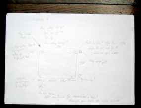
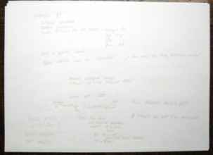
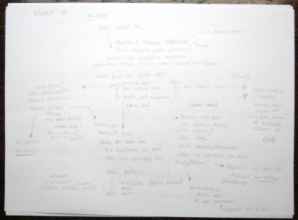
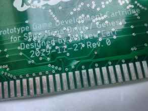
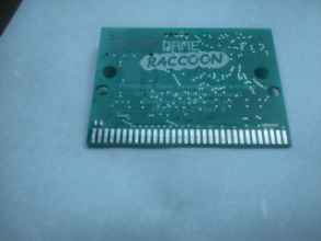
Let's start with some graphics

Let's start with some graphics. I'm going to try drawing some bricks. Then I'm going to immediately hate the bricks and try something else instead. I'm going to open up Photoshop and make a random noise texture and apply some levels of horizontal blur to it. Then I'm going to overlay it with itself offset and looped to create a seamless 32x16 texture. The colours of this image don't matter since I can apply any palette I want to it - and I'd have to do so separately when I import the data into the ROM. I've made a few copies of the texture and darkened them to create a 9 colour image. I can now load this into the Tiled tilemap editor to lay out my first draft of the game selection menu screen! As I mentioned, I can turn this image into a solid-coloured backdrop by making both the dark and light palettes the same to seamlessly fade from the title screen to the game selection screen without fading to a solid colour in between. The tegels encoding this layout have to be stored somewhere or calculated somehow. I could use fancy algorithms, but I decided to just store it all in ROM since I have lots of space. Don't waste time coming up with tricks to identify looping/modulo sections and their exceptions if you have space to store everything explicitly. It's a testing prototype anyway - I can't iterate if I'm working with a brittle algorithm. If I have a grid of tegels as a blob, I can export and re-export as often as I like. Let's chuck it in. The very first image of the Revision 1 menu, and it's looking fab-u-lous. Uhh... The tegel and the tile graphics are landing in the right place, so I'm making progress re-learning how the VDP operates. Those horizontal strips of garbage tiles are the results of my testing the Window Plane. I've filled the entire Window Plane with a visible garbage tile, and I'm testing to see if I can split its display over a discontinuous area by altering the VDP registers during the middle of the screen. I'm waiting for a specific line by testing for a specific Vcounter value (which contains the number of the on-screen line currently being drawn), and altering the Window Plane extent register at that instant. In this screenshot, the Window Plane begins anchored the top of the screen extending downwards, but in the middle of the screen I'm setting the Window anchored to the bottom of the screen extending upwards. At the end of the screen, the Window Plane is reattached to the top of the screen again. Together, the effect is to display the Window simultaneously attached to two different edges. The strange colours you're seeing are chosen so I can clearly measure when my changes fire, as I also change the palette at the same time. The black sketchy area is my changing the background texture palette to zero while the bottom-anchor is in effect. Right now I'm restoring the Window Plane to the top edge of the screen prematurely so I can see the effect and response time more clearly, but I can position either threshold wherever I need them to be and choose whatever window size I need. If I move the second change condition (that causes the Window Plane to be displayed attached to the top edge) to wait until the Vcounter is off the visible screen, I can choose to have the Window plane active only for the first N1 and last N2 rows of the screen. This is important, because it means that I can now selectively clip the display of Plane A at the top and bottom of the screen by using the Window Plane to disable it. This will allow me to display a scrolling list of games constrained within the dark region of the game browser screen! Mission complete! That's given me something to look forward to when I program the game browser screen. But first, the title screen. It's my lovely Game Raccoon logo, copyright and trademark me © ™ 2020! To squish this into the Mega Drive: • Resize it to the appropriate size. • Reduce it to an acceptable number of colours. • Encode it as Mega Drive graphical tile data and tegels. • Compress it, optionally. • Include the blob in the ROM. • Load the graphical tile data and tegels into VRAM. • Load the palette into CRAM. • Perform logic to display the logo nicely. First, I used Photoshop to add a nice border to it and fill in the letters. I also redrew the TM since it was rather small. Then I resampled it, baking in the border and fill layers as well as allowing the edges to become anti-aliased. I used Photoshop's Save For Web to save the image as a low-colour PNG which could then be loaded into Cearn's Usenti, the premier tool for handling tile-based graphics for over a decade. I manually swapped around some of the palette entries to make a nice gradient, in case that came in handy. To export these 16-colour PNGs as Mega Drive tiles, I wrote my own exporter in Python using Pillow. Python is the business for this kind of thing. Something that would take a master of C ten minutes to do can be done in ten seconds in Python by a buffoon. Mega Drive tile graphics are 4 bits-per-pixel, as each pixel can select one of the sixteen colours from the current palette line. 4 bits-per-pixel * 8 pixels per row * 8 rows = 256 bits = 32 bytes = $20 bytes, a value that comes up a lot when you mess with VRAM. It's good to manually calculate the correct size of a converted graphic on paper, since it's very easy to convert your graphics to a binary format and then realise later that the reason they're not working is that they're in the wrong bit depth and half the image is missing, something you may have caught if the output size didn't match the expected size. Opening the binary in a hex editor and manually converting a few bytes yourself is a good idea as well. Don't ask me whether the low or high nibble contains the leftmost pixel of the tile, I haven't a scoobily. While I was looking for the best method to retrieve the palette data from an indexed colour image in Pillow, I came across a classic piece of documentation in the ImagePalette Module. "The ImagePalette module contains a class of the same name to represent the color palette of palette mapped images." "This module was never well-documented. It hasn’t changed since 2001, though, so it’s probably safe for you to read the source code and puzzle out the internals if you need to. The ImagePalette class has several methods, but they are all marked as "experimental." Read that as you will. The [source] link is there for a reason."

Talking about tools

Let's talk about some other tools I use for testing Mega Drive projects (he says as if there's any ones other than the ones you've heard about). I use Fusion as my first emulator for testing things quickly. It loads fast and I know where the buttons are. If it doesn't work in Fusion, it will probably also break elsewhere. That might set some nerds hollering that I've got my logic backwards, but I'm not trying to do anything super fancy in the Game Raccoon menu, so if Fusion doesn't show something right, chances are I've made a basic mistake somewhere. I also have BizHawk ready, which is amazing and I love it. It's absolutely perfect for screenshots or lossless videos. I've tried Blastem and Regen, but I either couldn't get on with the interface or they crashed all over the place when I tried to do any debugging with them. If I recall correctly, I didn't use Exodus for the Instrument Maker as it might have predated it. In that case, I might have even used the debugger in MESS or Mednafen to help make it. The best Mega Drive emulator there is for Mega Drive work is Exodus. It's got everything, and I mean everything. The only thing I can't get my head around is how to get it to load and save workspaces correctly. I could spend half an hour arranging the windows how I like, click Save Workspace, and the next day Exodus simply won't load its own configuration back. It has a default set of configurations which work nicely enough, but I always have to drag out a few tabs to make things usable. The main video output display (and it's debatable which one that is!) doesn't seem to have any options to lock it to an integer multiple of the current resolution, which seems like such a strange oversight that I feel like I'm missing something obvious. This screenshot doesn't show nearly half of the windows that Exodus makes available to you and it's already filling both of my 1280x1024 monitors. The VDP window in the centre shows the state of the Mega Drive's graphics chip: • The panel in the upper left displays the contents of the Color RAM: four palettes of 16 colours. • Below that is a visualisation of the complete contents of VRAM shown as graphical tiles. As the Mega Drive always displays tiles using one of the four palette lines, you can choose which palette line you want to view the tiles in. You can see the textured backdrop tiles first, followed by the Game Raccoon logo. At the bottom of VRAM you can see some vertical stripes of garbage: this is actually the nametable data for Planes A and B being shown as tiles, since they also have to live in VRAM alongside the tile graphics themselves. • The upper centre panel shows the current values held in all the VDP registers, defining the nature of the current screen mode. These can be shown as numbers or in context. • The panel in the upper right shows the VRAM (the same data as in the lower left) as a hex dump. • The panel in the lower right lets you explicitly toggle the display of planes or sprites to allow you to verify the display of any part of the constructed display in isolation. Beneath the VDP window is the CPU debugger, which contains panels for register viewing, disassembly, RAM inspection, breakpoints and stepping. One helpful hint for Exodus is that the debugging stepping F-key shortcuts only work when the disassembly listing has the active focus. None of these emulators could reproduce the corrupted text bug from the Revision 0 menu, which is strange. As I said, I'm not doing anything fancy with the Game Raccoon menu system. Right now, all I want to do is load a bunch of tiles into VRAM and display them with a palette I've extracted and converted from the logo image.

The graphics working

Bwaha! There it is! One nice repeating blue background with a Game Raccoon logo on top. Now to get it scrolling. Scrolling on the Mega Drive is a little weird compared to other systems I've used. If I recall, both the Master System and the Game Boy Advance just have one value each for the vertical and horizontal scroll, and you need to set the value manually every line during the horizontal blank if you want a special effect to take place. The Mega Drive's VDP automates the generation of scroll-based special effects: the VDP allows you to specify whether you want the screen to scroll horizontally as one solid block, as a series of 16-pixel tall strips, or as individual independent lines. For these effects, the system reads multiple horizontal scroll values from a table that lives in VRAM to automatically offset or shear the screen as you indicate. Setting these offsets is the responsibility of the programmer, but allows for arbitrary, zero-cost parallax scrolling of both Planes A and B. Vertical scrolling is handled similarly by a table that lives in its own VDP memory region called VSRAM. It's easy to forget that these tables live in VRAM and VSRAM respectively - I spent a while writing to regular RAM expecting my horizontal scroll table to be memory mapped, which it of course isn't. When you get it right: Well, almost right. This is scrolling backwards! Different systems have different conventions for whether a positive scroll value means shifting the visible plane to the left or the right or up or down. Trial and error is all you have here. If you try to remember it, you'll get it wrong, and you've got more important things to think about anyway. If you stare at this for a few seconds, you might notice a strange flickering effect to the top right of the E of 'GAME' and below the two Os of 'RACCOON'. That is due to the way I've laid out the looping background tiles. I made the circular corner tile for the interface by copying and pasting the looping texture and then darkening them slightly. However, the looping texture is 32x16 pixels, and there's no guarantee that the tiles I pick to be the corners of the dark menu region will be at the same position within the looping texture's pattern when they're placed down onto the grid. This is only a concern if I choose to scroll the background modulo 32 pixels instead of by its full size, as I did to make the above gif smaller. The correct solution is to make new corner tiles reflecting the correct corresponding contents of the light background tiles at that position of the grid. Haven't done that yet. Okay. Time to boot this thing up on the real deal hardware. YEAH! The Game Raccoon logo is fading from white to its normal palette, and the scrolling background is scrolling as it ought to. It's a little strange booting up the Revision 1 menu prototype from the Revision 0 installed menu as if it were a game, but it's like a nice 'passing of the torch' style event. If you like. The bands of colour above and below the scrolling background are the background backdrop colour 0 being displayed in the overscan area. I've deliberately made it the darkest colour in the stone texture of the background tiles, but other games ensure that this colour is always black. I don't think Sonic ever does though: it just rolls with whatever colour ends up there. PAL players with miscalibrated TVs can see these above and below the game display at all times. Whiny PAL players from the Nineties whine about it. Game Masters* just get on with it and win. (* and Game Raccoons) What's even more surprising is that everything looks right. I mean the logo isn't distorted and the background is scrolling and looping correctly. Whatever I'd gotten wrong with the Revision 0 hardware or software to get the error with the corrupted text is no longer happening. That's really really good news. The major change I've made in my use of the VDP in Revision 1 is to use longword commands exclusively. To prepare the VDP for writing to VRAM, you have to first write a longword instruction to the VDP's Control port containing the address you to write to and a flag indicating which one of the address spaces (VRAM, CRAM or VSRAM) you're targeting. When I was programming the Instrument Maker and the Revision 0 menu, I was working off information that said it would be faster to write a single longword to the VDP to begin with, and from then on only write words when possible, relying on latching behaviour to maintain the value of the uppermost word. I either misunderstood the conditions where this applied (only within a single address space, maybe?), or the information was incorrect, but I think that this was the cause of my palette writing and text distortion problems in the Revision 0 menu. Revision 1 uses the explicit longword form of the instructions exclusively, and the palette and VRAM writes are working exactly as I expect. Yaaaaay! What's next?

Let's get some text going

The Revision 0 menu used a single 8x16 font called TrioDX, which you can read about in the Adventures in Revision 0 page. It's a lovely, Shining Force-esque font, but I don't think it's right for this menu. It's time to head back to OpenGameArt and have another nose for a suitable font. Here's a nice set of 8x8 fonts by usr_share licensed under CC0. I was specifically looking for a clean, linear-looking font that resembled the Street Fighter font, and usr_share's 'Saikyo Sans' deliberately imitates the Capcom style, which is exactly what I'm looking for. It only has uppercase letters, but that's fine: I'll just use the lowercase letters from 'Torus Sans' to create a complete character set. That was straightforward! I've used Photoshop to apply a gradient and a drop shadow to the font. That's probably set off some more nerdy alarm bells, but it's very easy to make both an axis-aligned dynamic gradient and single pixel dynamic drop shadow in Photoshop while maintaining transparency without introducing ugly aliasing. Use a harsh Drop Shadow and a Gradient Overlay from the Blending Options... Layer Style menu. After saving the result as a low-colour PNG, I can import it to Usenti and verify the graphics are residing within their cells correctly. I can also arrange the palette entries used so they coincide with the gradient used by the Game Raccoon logo so they can share the same palette line. Letters that have a gradient from white to a pastel colour are very RPG Maker 2000! (We love you, Don Miguel!) I've loaded the tile graphics to the end of VRAM immediately before my nametables, since the font will be used throughout the menu, unlike the Game Raccoon logo. I don't have any fancy system for organising my VRAM: I'm just placing things where I like manually. The Exodus tile viewer lets me view the loaded character graphics in the context of the Game Raccoon logo font. They're a little dark here, so I might try swapping the indices of the character graphics about in Usenti so other colours from the GR logo are used, or just dedicate a new palette line to text. You can also see in the Palette pane that the Game Raccoon logo palette on the second line has some repeated colours, which is not too smart. That happens when you blindly crush 8-bit-per-channel images into the Mega Drive's 3-bit-per-channel colour space, which is what my Python tools do. Because the Mega Drive has a vastly reduced colour space, colours that were similar but distinct in the original image may not have unique corresponding colours in the Mega Drive's colour space. I haven't set Usenti to work in a 9-bit colour space, so I didn't see this until now. I'm not going to waste time on it though. *chef's kiss* I had a string writing function in the Revision 0 menu stuff, but I decided to write a new one. Didn't take a minute, and it came out perfecto. I'm going to have to rethink this background. This text is kinda small; I can see why the main interface in the Shining games is 8x16. I don't really want to have to scroll through a whole screen of these little letters. I'm going to put an 8x16 font in as well. I was in two minds about replacing the TrioDX font used in Revision 0, but I decided to look for a cleaner, solid, straighter font again. In the thread community fonts for NES Dev on nesdev.com, I saw an interesting, clean font named 'Gsmplay_8x16.png' posted by tepples. The description says it was designed for a media player for the Game Boy Advance, so I believe it would be designed to look good at low resolutions and on low quality screens: perfect for the Game Raccoon and my PAL Mega Drive 1's RF signal. I asked tepples directly about the license for the font and whether he made it, and he confirmed both: I designed the GSM Player font myself. All my bitmap fonts are public domain, Creative Commons Zero (CC0). So I'm good to go! I want to make an aside about RF, come to think of it. In emulators, I see options for scanlines, and I see large guides and forum threads for using obscure cables to get better video from video modulations other than RF, even to the point of soldering in new connectors and potentially removing the RF modulator for space. What the heck is that all about, eh? RF is fine. It's lovely. It works on my Sony Bravia big-ass ancient first-gen HDTV just fine. What on earth is all the fuss about? Big fonts! Big prizes! I love it! I had a bit of a smug masterstroke here with the text rendering: I originally had an 8x8 writing function, then a separate 8x16 function, then figured out a neat way to extract the common line-of-characters writing function and parameterise it on the base tegel number so it could be used for the 8x8 font or either row of the 8x16 font. (The 8x16 string rendering function rendering each row of the text in turn.) One thing I really like about the 8x16 font is that it handles ascenders and descenders better, with the baseline of the font leaping around from letter to letter less. Compare the 'g' in 'Cartridge' between the two rows.

This is a good time to talk about palette fading

I want smooth fades between screens / interfaces. The Sonic series on the Mega Drive have a very distinctive style of palette fade to black between Acts and to white transitioning to and from Special Stages: Each channel is faded in turn with a small amount of overlap: first the red channel, then blue channel, then the green. The first time I saw this I thought it was a hardware quirk of the Mega Drive that meant that this was the only fade it was capable of. The fact is that they just did it to look cool! It also possibly looks better than attempting to fade all the channels at once. Manipulating the individual channels of a colour within a Mega Drive palette isn't easy. The Mega Drive has a 9-bit colour space, with 3 bits each for Red, Green and Blue. This means that where an 8-bit colour channel takes values from 0 to 255, the Mega Drive maps that same range to 0 to 7. The channels are stored in the nibbles of a word with the least significant bit of each nibble ignored. Because the colours are all combined together into a single value, fading out each individual channel like Sonic probably took a lot of effort! Having a table of values for fades sounds like the obvious solution, but it takes of a whole bunch of space even if you split it up per-channel, and then you have to worry about reassembling it. I'm going to write a function for writing an interpolated palette into CRAM which is N steps between two given palettes passed as arguments and I'm going to do it as naively as possible, using MULU on each channel and shifting things about. If it's too slow, I'll work on it, but I don't need the processor time for anything else. I used a very early version of this function to fade in the Game Raccoon logo from white and the background blue texture from black in that video above.

Drawing the buttons

I want pretty, obvious options with icons and text at the bottom of the screen, which means I need to draw myself some buttons! But what type? The 'Terminator'-like embossed text on the Mega Drive pad's buttons has always stuck in my head. In fact, it's possible the Mega Drive was the first console I ever saw! The B button is going to be the main selection button because it has TRIGGER written beneath it, as well as having the homing nub. If memory serves, it also maps to the primary fire when the Mega Drive pad is plugged into an Atari 9-pin-compatible system. However DO NOT DO THAT because there is no such thing. Don't mix joypads and systems. Don't ever do that. I'm going to draw myself a set of Mega Drive buttons. If I can't do that, I don't stand a chance at drawing an animated raccoon... I'll use the Game Raccoon logo palette again. Yuck. Alright, I can safely say I won't be drawing the captions myself - definitely sticking to the text layers for that. Also that button is teeny tiny; I'm going to redraw it bigger. Oh that's lovely. Yep, very pleased with that. That is most definitely a button with a gently concave interior. Let's draw some letters. Can you tell the difference between these two? The A on the left is the same width as the other characters, and the A on the right is one pixel wider to fit within the boundaries of the button more symettrically. It looks miles better, I reckon. I've decided to not have a triangular A to match the embossed lettering because... I wasn't looking at a picture of the pad at the time and this just felt more consistent. A trio of freshly-minted bouncing buttons ready to assist you in your game development endeavours. But we can't forget Start! Aha! There we go! I could write START beneath it, but I don't have the horizontal resolution necessary to make it look nice. I think the context, as well as the other buttons being shown beside it, will be clear enough. I plan to map Start to 'boot currently installed image', so if anybody powers up their Game Raccoon and can't figure out what the 'mystery hotdog' is all about, it'll come to them eventually. Most systems with sprites have an array in some RAM containing fields for all the parameters of all the available sprites, such as tile number, position and flip flags. The Mega Drive adds an extra layer of complexity in the form of the linking system. This explanation will be poor because I don't fully understand it myself. The VDP selects what sprites to draw starting with sprite 0, then reads that sprite's Next field and jumps to the sprite at that index. Successive sprites form a chain, until it reaches a sprite whose Next is equal to zero, and it stops gathering sprites. There's probably a really clever reason for this system involving being able to enable and disable large series of sprites with a single memory update, but I can't figure out a reason why you'd want to do that and not update the parameters of all the rest of the sprites as well. Because of that added field, it's tempting to set the Next fields to an ascending sequence to enable all the sprites and then forget about it, disabling sprites that aren't needed by placing them outside the visible frame. I don't know whether that would have any negative consequences. A more involved alternative would be to write your own sprite paramters layer that only contains the attributes you want to consider, and have a transfer function that translates those values and populates the VDP sprite list. Here's some alternate palettes for the background to test fades. My palettes need to be part of the RAM-resident image if I'm going to be doing fade effects during isolation (or alternatively I could copy only the currently fade source and destination palettes to RAM just-in-time). As I add more graphics to the project, taking the palettes from each source image in turn is getting too confusing and error-prone. To consolidate things, I've written a palette export script that takes in a 16x16 PNG with palette lines written as truecolour pixels and outputs a block of Mega Drive colours. Now I can see and edit all the available palettes in one place and do adjustments individually or en-masse. Remember to clear the currently written tiles before drawing a new string, or you'll end up HandsBOOTng... yourself. That final screenshot -says- Ready, but I don't believe it. I've got to manually place these text captions and sprite graphics using constants in my assembly code. There's no trick to it. There we go. Super neat! I think perhaps I underestimated the size of the buttons when I redrew them to be bigger. Ah, what the hell. 1,000 foot interface and all that. It'll look great on the TV. The PIC firmware now uses the bidirectional register to send back status codes when returning from the startup handshake, directory record cache regeneration and game installation instructions. I've wired up the title screen to send the handshake and wait for deisolation to read the response. Depending on the response, a different caption and option set will be displayed. The red screen is designed to put THE FEAR into unsuspecting Game Raccoon users, much like a Nintendo error screen. This means there's more error checking code needed, with appropriate defines shared between the PIC and 68000 firmwares. I've seen a few pages of kernel C code, and it's always written in a clipped style like someone's skipping through spoken cutscene dialogue in an RPG. My own preference is for long, descriptive symbol names, though I'm willing to concede that these symbols might be a little too long for some. I've got to keep track of what options are allowed for each response. If the SD card isn't accepted, you can only boot the current game. If the SD card is alright, you can browse it or head to the About screen. I don't strictly need one, but I want to write some Sick Greetz and include the obligatory-to-the-point-of-parody "Not produced by or under license from Sega Enterprises Ltd." message. I also had a brainwave - I should put the menu firmware update option as a secret within the About screen so folks won't mess with it accidentally. It saves me having to figure out weird exceptions on the game browser screen, and works well with my mental model of how the screens link together. I've also got a plan for how I'm going to get all the text on the About screen. I'm going to just store it as a blob of tegels prepared by a Python script during the build process. That'll let me include the build datetime as well, in case that's ever useful. Here goes! I got the tegel tile base index number wrong. Blah!

TIMING CONSIDERATIONS FOR TIME WRITES

What is the minimum delay before it is safe to check for deisolation? I designed the Game Raccoon's hardware to be as safe as I could: preventing any possibility of contention on the Mega Drive's address or data buses or on the internal Game Raccoon board address or data buses. • The address and signal transceivers on the board prevent the Game Raccoon from outputting onto the Mega Drive's address bus. • The Game Raccoon can only ever output onto the Mega Drive's data bus in response to a signal from the Mega Drive itself. These signals are post-transceiver and are disabled by the PIC's isolation signal as well. • The PIC's isolation signal disables the address and signal transceivers outputting into the internal buses. It's the responsibility of the PIC firmware to not output onto the internal address or data buses unless isolation is established. When the Mega Drive menu firmware contacts the Game Raccoon board through the !TIME register, the following sequence of events takes place: • The move.w d0,(ABS.l) instruction takes 16 68000 clock cycles. • The write cycle takes place during the last 4 of those clock cycles and the 68000 immediately begins executing the next instruction. • The write cycle consists of the data being presented, then !TIME then !LDS being lowered, then !LDS then !TIME being raised, then the data bus becoming idle. • !TIME and !LDS are propogated through the signals transceiver on the PCB. • These are decoded by the logic section on the PCB: first through the OR gate to determine the required action, then through the AND gates to control the necessary devices. • The output of the OR gate is also routed to the CN0 input, which causes a Change Notification interrupt on the PIC on the falling edge of REGISTEREXTERNALCLK. • The PIC context switches to the interrupt handler. • The interrupt handler clears the pending interrupt flag and sets the 'proceed' flag. • The PIC sets a GPIO to enable isolation. • The isolation signal charges and reaches the address and signals transceiver to engage isolation. There is a timing consideration here: the falling edge of the post-transceiver decoded write wakes up the PIC while the 68000 is still performing the data write into the !TIME memory space. The PIC must wait for this write to continue before manipulating any GPIO in order for the write to complete successfully. This interval is the time from the 68000 sending the !LDS signal during its S4 cycle until it is raised by the end of the S6 cycle. In my notes I'm working from another source than the original Motorola documents or the Freescale modern replacements, but it's a longer interval so let's use it. This interval is 0.2632 microseconds long, not counting distortions applied by the Game Raccoon board's transceivers and logic section. These are measured in nanoseconds (0.001-0.010 microseconds), so are more-or-less irrelevant to this calculation. So 0.3 microseconds after !LDS falling edge, it should be safe to isolate the cart. The PIC executes instructions from the handler >= 0.25 microseconds after the interrupt event. The PIC interrupt handler has 9 instructions inside it, taking at least 11 x 16 MHz (FCY with FOSC at 32 MHz) accounting for RETPIE's longer execution time. Following the sequence of instructions necessary to engage the isolation, the PIC will have engaged isolation 2.2 microseconds after the original write began. So the PIC's response will be 2 whole microseconds beyond the point where it could interfere with the write, which is good. This reponse speed is also why the register is used rather than have the PIC attempt to read a value written onto its data pins directly from the 68000 (discounting the possibility of a parallel slave mode designed for this purpose, which I'm not using). This 2.2 microsecond duration is also the minimum time the 68000 must wait before testing for isolation, since if it performs the test before this interval is over, it will be reading data from the cart before isolation has been applied, and will incorrectly detect that the cart has returned from isolation when in reality it hasn't yet begun. Dividing 2.2 microseconds by the length of a 68000 cycle gives 16.721 cycles. The move.w (....l),d0 instruction takes 16 cycles, with the read occurring in the last four cycles, so at least one nop (taking 4) is required after the !TIME write before the 68000's read of the cartridge data for the isolation test, preferably more. This exciting thought experiment is rendered a little suspect by the potential, unquantified interference or even replacement of the normal cycle process by the Mega Drive chipset itself, which could introduce any amount of deviation from the textbook 68000 timings, but I'm happy with these numbers. I think.

Some notes about the design and controls for the game browsing menu

Here's some notes about the design and controls for the game browsing menu. In the lower left is a sketch of the behaviour I'm using to split the Window Plane. Calculating the logic for ensuring the scrolling of the game list works correctly and doesn't allow scrolling beyond the ends of the list as well as working correctly when the list doesn't extend beyond the screen is intricate stuff. You've got to draw in new tiles immediately before the new row is scrolled into view, and take into account where the line of tiles would reside within the logical plane given that it's going to be displayed at an arbitrary offset. It's like a circular loop of paper in a receipt printer that's going round and round and showing you a specific section at a time and printing new lines onto the paper before they come into view. I rewrote the directory record cache display and sorting algorithms from scratch and everything worked first time, which was nice. The old code from Revision 0 was very confusing, and clearly the product of trial and error rather than design. It takes a while to sort a large directory since I'm using a simple rather than a smart algorithm, but I don't care. I've added a new field to the directory record containing the size of the game in 64 kibibyte blocks. This lets me come up with an estimate for the writing time of the game so I can display a timer on the game installation screen, at the cost of two pathname characters. How many nested directories do you have? :) I have successfully defeated the code malaise and have begun working on the game browser. The left image should look familiar: the X characters are filling the Window Plane, but are simultaneously attached to both the top and the bottom edges of the screen due to my manipulating the registers mid-way down the screen. Plane A will only be visible in the unobscured region where the Window Plane is not present. The right image shows the game list displayed on Plane A within the hole within the Window Plane. Right now it's showing the full directory cache name of each entry in the list; I haven't yet implemented the 'get pointer of string from rightmost slash if present' function yet. Also the three entries at the top are actually directories, but are not yet shown in a different colour - that is, palette line. I edited the graphics for the capital M so that it didn't collide with the right edge of its tiles, so it didn't merge together with the adjacent 2 in YM2612maker.bin like the W and D do in TANGLEWD_demo.BIN. I need to edit that W, and make sure I import the new graphics correctly. I'm not a fan of how dark the periods and underscores are, so that's something else I should keep in mind. The single period in the top left of the menu area is the current path, currently the root .. I have to implement scrolling, which means first I need a cute raccoon hand cursor sprite. Like this one. Is he wearing gloves? Does he have blue hands? Who can say! It'll do for now.

How do all these screens fit together?

In Game Raccoon world, all roads lead to Pringles. I've written the following independent screens: • The Title screen, which handles the initial handshake. On success, you can choose Boot, Browse or About. On failure, you can only choose Boot. • The About screen, showing the about text. You can choose Browse or the secret reflash option. • The Reflash warning screen, showing the warning text. You can choose to Reflash or power down the system. • The Regeneration screen, which handles the directory record cache regeneration. On success, it moves to the Browse screen. On failure, it shows an error and hangs. • The Browse screen, which shows the contents of the directory record cache and lets you navigate and select an image to flash. You can choose Boot, Select or Parent. Select moves to the Installation screen. Parent navigates to the parent directory. • The Installation screen, which shows a countdown timer until the installation has completed. On success, you can choose to Boot. On failure, it shows an error and hangs. I've decided to use simple fades to a solid colour between these screens for now. Having a scrolling background behind the game browser would be too distracting, I've decided. I could always put the effect back in later, but that reminds me of a quote that I believe definitely applies here: 'there's nothing permanent like temporary'. If something functionally works and I've no reason to change it, cosmetic upgrades are going to be right at the bottom of the tweaking pile unless there's a true need for something to be changed. I wrote them in the order Title, About, Reflash warning, Installation, Regeneration and Browse. I programmed the menu to automatically regenerate the directory cache every time the user selects Browse from either the Title or About screens, but there's no strict need for a regeneration to take place before allowing the user to see the menu. My original design when I was working on Revision 0 was to have Regenerate as an option that could be selected from the game image browser. However, allowing the user to head to Browse from the Title directly, or having the game image browser open immediately upon power-up like in Revision 0, opens the possibility of the Mega Drive menu firmware attempting to read an invalid directory cache. Unfortunately, there's no reliable way to detect that the contents of the directory cache in the Flash are entirely valid before displaying them, except to command the PIC to erase and reprogram the cache with known valid entries. In the name of ensuring the cart is user-proof, not allowing a transition to Browse without regenerating ensures known-good states throughout. One sneaky trick I realised I could use was to combine the game installation and menu firmware installation screens into one: the only difference in terms of functionality is whether a directory record cache index value or a magic number signalling menu reinstallation is sent to the PIC. If the installation was a menu replacement, the menu shows 'Please restart your system' message when complete, since you really, really ought to power off the system and boot afresh into the new menu system after reinstalling it. For a game, it shows a Boot option. The Installation and Regeneration screens are very basic in terms of functionality, since all they have to do is send a message through !TIME and wait for deisolation to receive the status response. Right now they're very, very basic looking - there's a great big intentional cartoon raccoon-shaped hole that I would really love to fill up with an adorable mascot rummaging through a box or eating SD cards or something like that. I need to plan that out and talk it over with an artist. I modified the directory record cache format for files to include a field at the end containing the size of the file in 64 kibibyte blocks. Since I know the length of time it takes to write Overdrive from recording it earlier, and I know that every Flash sector takes the same length of time to format and reprogram, I can calculate a heuristic for how long a game should take to install, and show a progress bar on screen to give the user some reassurance that something is happening. I put the LED indicators onto the PCB so I'd know the board was working and so I could use them for signalling while writing the PIC firmware, but I've become very attached to their blinking sequence during programming, and the way they alternate between the solid green for formatting and the chattering for programming and verification. I'm going to leave that behaviour in, and suggest to users that they turn their TV off while reprogramming the Flash. The yet to be added awesome raccoon animation will be adorable, but it might get old if you're doing a lot of testing. You do -not- want screen burn from leaving the Game Raccoon menu on. I've already got a lit rectangle visible on my Sony Bravia old-gen HDTV from playing Mega Drive games in 4:3 aspect with side black bars. I've switched to the screen-filling Zoom mode now!

How does it look in the emulator?

Definitely getting there. I'm liking this a whole lot. That scrolling is exactly what I intended. The interface is flickering a lot when I navigate directories though, I need to look into that.

Talk about adding in error and status reporting in the PIC firmware

It's time to test out the bidirectional communication register on hardware! It didn't work. :( When I tried it on hardware, the title screen always reported an error reading the SD card. I thought I'd gotten the logic wrong and ruined the entire Game Raccoon board somehow, but that didn't make much sense - Awesome Possum and Misplaced worked fine with the Revision 0 menu on this board, so even if I couldn't get the PIC to report values back correctly, I haven't ruined any existing features with my new logic section. I looked through the main.c for the PIC firmware to make sure all of the new code I'd written to report errors and status was correct and everything seemed fine. Stepping through with the debugger led me to here, which was the cause of the error. The code on the left is faulty, the code on the right is the fix. The error I'd made was assuming symmetry with the conditional directly above it. The first conditional branches on failure and exits, but the second conditional branches on success. The correct sequence is: • The first conditional aborts and returns ERROR if the result of f_opendir is not FR_OK. • From here, I assume ERROR anyway until a good state is reached. • The second conditional only allows attempting a good state check if f_readdir is FR_OK. Otherwise skip the test and keep the current ERROR state. • If f_readdir is FR_OK, then the error state can be upgraded to EMPTY rather than ERROR. • Only if the fileinfo.fname field is nonzero can I upgrade the error state to a valid OK. • The final adjusted error state is returned. This was the only change I needed to make to get the Revision 1 PIC firmware fully functional with status reporting!

Fully functional doesn't mean perfect though!

I've got the gizmo running game images wonderfully, but there's still all kinds of bits and bobs that need to be looked at. Let's have a goose at the notes I made up in a hurry in the testing room besides the big TV. 68k: • good: Fixed start not working on installation screen: i'd mixed up CHOICE_ENABLED_BOOT (the power-of-two constant) with CHOICE_ENABLED_BOOT_BIT (the bit position) This was a bit embarassing, and meant that I couldn't boot games from the installation screen! I'm using btst to check for membership within a set of bits indicating what options are currently available. The index of the bit within the set is not the same as the numeric value of that bit placement (value=power(2,index)), so my menu didn't work. • good: Fixed scrolling of Plane A being left askew when entering installation screen. I'm scrolling Plane A to navigate the game list on the Browse screen, but I forgot to reset the scroll value when I transitioned to the Installation screen, meaning that the 'BOOT' caption appeared at a random Y coordinate on screen based on the scroll position of the game list. • good: Removed some temporary $0000 response forcings on !TIME reading, which were there only for emulator use. This should fix weird handshaking and regeneration errors being ignored. As there's no emulator that simulates a Game Raccoon cartridge, I have to put in ugly substitutions that force faked return values whenever I interface with the !TIME register to attempt to detect isolation. When I first took the menu firmware to the cartridge, I'd forgotten to remove these simulated responses (despite leaving a comment in the code saying ; Remove these simulated responses), so the behaviour was very strange. I've since added conditional assembly directives to the 68000 firmware that simulate return values and isolation durations, so I can compile separate versions of the menu software with and without cartridge hardware simulation so I can test the menu software and raccoon animations in emulators properly. • good: Also made it so that d0 is loaded to longword zero before reading word from !TIME. I'm paranoid about the upper word of my longword register values when programming in 68000 assembly. I treat everything as longwords as much as I can, so before I read a word from !TIME, I ought to clear the upper word to zero first in case I do maths or a longword literal comparison on the value. • good: Fixed ugly fade state for palette line 2 making yellow text suddenly ping into existence when changing from regeneration to browse. I have a small state machine handling the state of the fades between screens. I can set the source, destination and speed of the fades for all four palette lines independently. If I forget to set a line, the colours will remain constant while the rest of the screen fades: when I fade to a solid colour, it isn't an overlay appearing on the screen but every palette colour simultaneously moving towards that value. • good: Moved raccoon hand to top of list instantly during the momentary delay when sorting the file list after a directory change. There's a momentary delay when the RAM-resident part of the Game Raccoon menu navigates into a new directory, copies the list of the addresses of directory record cache entries into RAM and sorts them alphabetically. Since I haven't written the sort as a coroutine and interrupts are unavailable, the CPU is committed to sorting the list and the mid-screen Window Plane split can't happen. It's not a problem: Plane A should be completely blank at this point since the current game list is being redetermined. I just need to ensure that the Window Plane is being displayed in the lower half of the screen so the button captions don't disappear. Resetting the hand cursor to the start of the list when changing into a new directory prevents it from landing outside the bounds of the new directory if it's smaller than the previous one. I could store a stack of cursor positions as the user navigates into a deep tree so their previous cursor position is restored whenever they choose Parent, but I haven't. • bad: need to blank YM state to silence GR when pressing reset during a game. • bad: need to recalculate installation gauge timings. ???????? • ----- cannot rely on 224 has a good vcounter waiting line, it appears that on my mega drive it is visited twice. I need to look in the Exodus debugger, configured as a PAL Model 1 system, and see what the exact route the number takes is, and draw a new graph on paper. • ----- need to make a constant for this line? Or maybe do two waits- one earlier on a line that is definitely visited only once? These two are very interesting! I'll write about these in a moment. The PIC side went a lot more smoothly: PIC: • check this!! Fixed incorrect condition for detecting correct SD card state- a != should have been a ==. As above! • I think the rest of the PIC code is totally reliable, nothing weird is happening and I'm getting sensible errors when I try to write, boot or do regeneration with a card out. One unexpected error that came up wasn't an error at all. Or, rather, it wasn't a mistake. I copied a whole mess of homebrew nonsense I found on github and some other archives, and the Game Raccoon menu firmware started complaining during the directory record cache regeneration that there too many files on the SD card. Turns out that, yep, I had indeed put too many files on the card, and the error reporting was accurate and functional! I had to edit the PIC firmware to increase that limit. I might have put it to a low number to free up more Flash space on the Boot partition for some reason I can't remember, but I think it was more likely that I was just intended to test the error reporting and forgot that I'd set it. Fixing errors on the PIC 'in the field' is annoying since it means I have to use MPLAB on my poor TV computer, get out the PICKIT programmer device and put it into the fragile programming header on the cartridge. Let's look into those two 'bad' errors in the 68k code.

It's the right time to argue about time, we do have the time

At first, the installation screen didn't have any progress bar or timer showing how long was left installing the current image. Because the Game Raccoon hardware currently programs at a rate of 90 seconds / mebibyte, it takes six minutes to write the largest possible image size. Although the LEDs let you know the PIC guts are still doing something, a visual report of the progress would be welcome, and possibly very stylish. I improvised a progress bar first using the string writing code and the - and O characters: using a bit of mathematical wizardry, the dashes are slowly replaced with letter Os as the installation completes. Entirely unintentionally, all these Os appearing in a row makes the screen resemble legendary Amiga backup tool X-Copy. Watching little letter Os appear across a dotted line still isn't very informative or interesting, so I scraped together a simple minutes-and-seconds timer in a hurry, which worked first second time, despite me programming it on the wrong computer in a rush! Both the progress bar and the timer report entirely fantasy progress by the way: there's no status reported by the PIC until the installation has completed successfully or failed somehow (f_read fail, verification fail, etc.). It's assumed that no news is good news until the actual good news arrives. If somehow the PIC entered an infinite loop while reprogramming the Flash then the progress bar would fill, the time would reach zero, and the 68000 RAM-resident firmware menu would sit there waiting for the cart to come out of isolation indefinitely. I don't think there's any way that could happen under normal circumstances. I could make the PIC report the successful programming of each sector in turn, coming out of isolation every five seconds, which would make the progress real rather than assumed and also give the RAM-resident menu code an opportunity to read some data from the ROM (for whatever reason - most likely reading some more animated raccoon mascot frames?). The timer worked beautifully... but not accurately. It was absolutely, completely wrong, for no good reason. It would count down, hit zero, and then linger there for minutes at a time before the success code was returned and the installation completed. The code was fine, the maths was fine. Everything was fine, but it didn't work. With some assistance from my brother, a stopwatch and a lot of mental arithmetic, I calculated that the timer was advancing at twice the rate it should. (That's '100% faster', '200% as fast', or 'one time too many' if you like.) The timer is based off a calculation of the number of frames the Game Raccoon RAM-resident menu code expects the installation to take based on the number of Flash sectors the directory record says the image requires. The only thing that decrements this value and advances the timer is the detection of a new frame being displayed on the screen, so either I've made a big clustermess in my timer numeral calculation code, or, for some reason, the menu code is detecting new frames at a rate of 100 Hz instead of 50 Hz. Because the 68000 interrupt vectors are not available during isolation (since they're located at a fixed address in ROM space, which is inaccessible during isolation), I can't rely on interrupts at any point in the menu firmware. This means I have to detect the beginning of a new frame being displayed by means other than the vertical blank interrupt. The simplest alternative is to continually read the vertical display counter and spin within a loop until a designated line is being drawn. So that's what I did. Unfortunately, the Mega Drive chipset hasn't made it as easy as that. The current line number is read from the VDP as an unsigned 8-bit value, but it's used to report all the possible lines of the PAL display, of which there are more than 256! The counter starts at 0 at the top of the screen, and travels down through 224 at the bottom of the standard height screen through 240 (beginning the vertical blank region) to 256-returned-as-0. Then it counts up to below-3 and snaps back to 202, then loops uniformly forward until line 0 again at the start of the screen. What I didn't account for is that this looping behaviour means that line 224 is encountered twice, so you can't rely on it alone to detect when the vertical blank region begins. If you had a loop that waited for 224 and incremented a counter every time the condition was met, it'd advance at a rate of 100 Hz, just as my clock timer does. The solution to this is to wait for a line that's known to only be reported once, like 201. If it's critical that the processing doesn't begin outside of the vertical blank, then you can wait for 201 and then wait for 224 immediately after. A better idea would be to do something non-graphical in the 201-224 region between the waits rather than wasting the time, if you can. In the rightmost pane of this screenshot, you can see the results of writing the current Vcounter value to increasing addresses in RAM every time the value changes. Bear in mind that this screenshot is demonstrative, not definitive: it shows the expected behaviour of the Vcounter as emulated by Exodus based on analysis, not the correct behaviour as read from a real system. Relying on emulators alone is how you get games that don't work on hardware. :) Since I was accidentally working with a 100 Hz update rate instead of 50 Hz, all my scroll and fade timings have to be re-done. That's fine, they were looking kind of slow anyway. The visuals are, as I said, all temporary, and subject to the damning eye of somebody knows how to design worth a fig. I intentionally made some of the fades slow so the raccoon mascot could wave to you when he was done rummaging through his box - I need to remember that.

I have no idea how the Mega Drive's audio hardware works

One bug that remained in the Revision 1 menu is that it doesn't initialise the sound chips when it starts. I don't intend to add any sound effects to the menu, so that might not sound so bad, but that doesn't take into account something I'd missed: when you press the reset button on the Mega Drive, the system reboots, but doesn't alter the state of the sound chips. This means if you're playing some fancy homebrew music disk that's blasting out music on all ten channels, then when you hit that button, all the sound chips will linger in whatever state they were in when the button was pressed, blasting out solid, unchanging tones forever until the next game image is booted. That's annoying as heck, so I've got to fix it. If I managed to convey my confusion about the Mega Drive's video hardware correctly before, it's time for the sequel: I don't have any idea how the Mega Drive's audio hardware works. Well, that's not true. I can remember that the Mega Drive has a YM2612 chip with 6 channel FM sound, and a SN76489 chip with 4 channel PSG sound (3 squares, 1 noise). Both of these chips are available for use by Mega Drive games, so I'm going to have to figure out how to manipulate them both. I looked through my Instrument Maker code, but it isn't very explicit about how the sound works, since its job is to simply shove numbers from the graphical interface into the YM2612 without any understanding of their function. http://web.archive.org/web/20190209132123/http://www.smspower.org/maxim/Documents/YM2612 http://web.archive.org/web/20200113150213/https://www.smspower.org/Development/SN76489 First, you must know that neither chip is directly accessible to the 68000 unless the Z80 CPU is disabled and the Z80 bus made available to the 68000. Then you can send register change commands to the SN76489 as you would on a Master System. Silencing the SN76489 is a simple matter of setting the attenuation value of all the channels to the maximum value. For the YM2612, it's a whole bucketload more complicated: • There are six channels, split into two groups of three controlled through different memory mapped addresses. • Each channel has four operators which are combined together in different arrangements (named 'algorithms') to produce the final output. • Each operator within each channel has a whole bunch of different fields controlling its envelope. • Each operator within each channel has its own note on/off state. And: • Before writing to the YM2612, you have to verify it is ready first. To silence the YM2612, I'm sending 'note off's to all the operators of all channels, and setting the TL (Total Level) of every operator to the maximum (like the SN76489, this is an attenuation value). This should result in full silence on all channels. And whaddya know, it works! No more sinister booping and hissing during installation, yay!

Let's compare the Old and the New!

It's night and day, right? :D The old, hackerish menu doesn't look like something you ought to trust, but the new menu is just itching to let you play some crazy new Mega Drive game from 2019 that you've never heard of. It just needs an adorable raccoon to fill in those blank spots to help you along.

I got frustrated at not being able to draw a cute raccoon so I did arrows instead

I got frustrated at not being able to draw a cute raccoon mascot, so I draw some little pixel arrows for the menu system at last. These were in my sketches earlier, I just hadn't put them in yet. That's very snug and neat, isn't it? I like that a lot, yep! The left sketch is from April 23rd, but I'd totally forgot I'd drawn a design months earlier for Revision 0 on October 27th last year! The design hasn't changed all that much. I don't have a NNN/NNN counter showing how many files are in the current directory, since there's nowhere to put that, and it's kind of useless. I don't have a text caption showing the currently installed game either. That would've been a bit of a funky feature. A waste of non-volatile space, and I'd need to format it every time the cart writes a game image to the game partition. If you want to know what you've got installed, just press Start, you know? Though, it would have a bit of use in letting you distinguish multiple versions of a game in progress if you put the version number in the filename. The mystery hotdog is intact, though absent a caption on the final layout. The Net Yaroze menu has its arrows on the left near the initial letter of each line, but I prefer them on the right, where they'd usually go in a GUI interface like Windows or Workbench. The Net Yaroze menu has a lit green rectangle backdrop behind the currently selected game item, which the Game Raccoon doesn't yet have. I don't think I need it. I think I could implement the effect with sprites if I had to, but having booted into the menu many times at this point on a real system, I've not had any issues with being able to tell what game I've selected. When I have a better idea of what the Game Raccoon mascot character looks like, I can redesign his cursor hand to match. The cursor is a little twitchy, but that's intentional to make scrolling simpler to implement. It's been repeatedly suggested that I add full page skipping on the left and right buttons on the D-pad. I'm not going to do this for a few reasons: • It's confusing to program. • The D-pad on a Mega Drive pad is very whiffable. You don't want to accidentally skip pages when you're navigating up and down the game list. • You shouldn't have that many files in one directory anyway - they'll take ages to sort! • I don't want to.

Misadventures in the Demoscene!

According to the demoscene archive and forum pouet.net, "Demos are the things that happen when people who are interested in computers sit down together and make something fun and spectacular and challenging to program. They work on it until it becomes a final work of art, then they pack up their sleeping bags and travel to a demoparty where they enter it to a competition. That's pretty much the gist of it." There are demos are almost every kind of computer and console there is. Even though there are no official means to develop for the Mega Drive, no tools (even though any assembler will do! It's the know-how that's the problem...) and few straightforward ways to present game images to the Mega Drive hardware (like, say, the Game Raccoon!), there are more than a few demos for the Mega Drive (and the 32X, the Mega-CD and the Sega Mega-CD 32X). Pouet lists 90 demos (a.k.a. 'prods') for the SEGA Genesis/Mega Drive platform. Excluding Overdrive and MD-NICCC as I've tried them already (and Overdrive 2 since it's too big to fit on the Game Raccoon), I've picked the top fifty prods from pouet and tried them on the Game Raccoon! Demos that work: Blowfish by Planet Earth. Datastorm 2014 Invitation by Genesis Project. Stuck Somewhere in Time by Up Rough, Insane & Titan. Bassfish by Speckdrumm. Awaken by SigFLUP. Featuring "POLYGONAL POLTERGEIST" and the ever-spooky "GREETZ GHOUL"! *blurrrrps up letters* Red Eyes by Kabuto, Exocet and Remute. FMV running on an unassisted Mega Drive! 3D graphics! Big-ass robots! 2048 on Sega MD/Genesis by Titan / oerg866. The game of 2048 is the devil's own invention. It was all the rage a few years ago and I never beat it. I was reminded of it by unrelated reasons earlier this year and tried to win it and couldn't. You can spend almost an hour getting yourself up to a position where you have sufficient numbers on the board to add up to the 2048 tile, but then something random happens and you instantly lose. NOT TODAY, FRIEND. Grey screen with no music by K-Storm. There's probably a very long-winded and interesting reason why this prod exists, but I don't know it. Sadly, by definition it's in the top 2/3rds of all Mega Drive demos in existence since it boots at all (and, hey, it works perfectly!). Jason Scott Birthtro by Planet Earth. This demo works best booting from the emergency boot, for some reason. Merry Christmas 2012 by SigFLUP. The music in this one sounded very strange and required emergency boot to get started. MDEM's First by MDEM. Lots of great effects; an AmigaOS homage, hooray! Some glitchy effects, some don’t seem to work, but there's some lovely FMV and sampled sound! Strange TV by Zephyr. It's hard to tell if this one worked very well. It's very rough in some places but that might be the style they were going for, with their Max Headroom intro and all. It is called "Strange TV". Xmas 2013 by SigFLUP. Needed emergency boot. These ones worked but I didn't take any pictures: New Year 2010 by Gigasoft. Worked, but seemed to work and sound strange. Tiido's Mega Drive Music Cart by Tiido. I also tried Z80 MUSIC by MIKE-STAMP (aka Z80MUSIC by Michael Stamper (v20091223) (PD).bin), which worked fine! I had a nice conversation with the author about it, too. :) There are five demos by Limp Ninja in my list, of which only two of the vertical line effect demos worked. Smell Those Douglas Firs, Bad Apple and After either showed a black screen or crashed within seconds of starting. Demos that don't work: Work Without Rules by Battle of the Bits. Malabars Bumper by Resistance. Travel by Resistance. The Spiral 50Hz by Resistance. The Spiral 60Hz by Resistance. ZSENILIA by Resistance. Day Trip by Planet Earth. Fullscreen NICCC2000 for Mega Drive by Resistance. Silly Venture 2019 Invitation by Mystic Bytes. The Art of Leonbli by Resistance. Zombie by K-Storm & Los Tacos De Mexico. Smell Those Douglas Firs by Limp Ninja. BadApple!! by FLM. YM2612 Live Player by K-Storm. UFO Micro-demo by ALKO. Dekadrive by Dekadence. Hack The Internet by K-Storm. Bad Apple Party Version by Limp Ninja. After by Limp Ninja. Sega Point by Oerg866. Tape21 by K-Storm & Los Tacos De Mexico. Vampires by K-Storm. VilQ by tehKaiN, Axi0maT and AceMan. VilQ Adventure by Axi0maT, Koyot1222 and AceMan. Most of these would show a black screen even on an emergency boot. Some would show the telltale single frame glitch of several tiny boxes running along the screen on start-up, like a lot of the malfunctioning homebrew games do. One or two will run for a few seconds and then hang, or have missing music. Looking through these in Mednafen, I can see some patterns: Resistance did quite a few of them, and SGDK appears in the thanks a lot. Only one or two complained about being run on an (emulated) 50 Hz machine, and when they do they do it explicitly, showing a message. Red Eyes complained that the timing in Mednafen was too inaccurate to continue, so I'm really chuffed that it worked on hardware through the Game Raccoon. There's a bunch of demos that I'd love to try by Censor Design on pouet. They're listed as being written in 1991-3, which predates Sonic 3! It's weird to think of Mega Drive hacks and demos being written on Amigas and Ataris at the time (best computers ever, and as a bonus the assemblers would be compatible) with no documentation whatsoever. I downloaded them, copied them to the SD card, stuck them in the Game Raccoon and... nothing. They run in emulators, but not the Game Raccoon. Why could that be? I opened a couple of the demos in a hex editor and didn't see the standard Mega Drive header or anything like it. How bizarre! The extension .SMD was a clue: although it might be expected that it stands for 'Sega Mega Drive', it also can stand for 'Super Magic Drive', a cartridge copier from the nineties. The Super Magic Drive can rip game cartridges to floppy disk and copy games back from disk into its internal memory for play. .SMD is the Super Magic Drive's own format, which is not the same as a flat Mega-Drive-compatible binary image. An .SMD contains a header of its own, indicating the file size, SRAM type and some other properties. Beyond this, the game image is broken up into a series of 16 kibibyte blocks, where the high and low bytes of all the words in the block are split into two 8 kibibyte sub-blocks containing all the high and all the low bytes respectively. Coincidentally, splitting the 16-bit data words of a Mega Drive image into separate low and high bytes is a necessary step for using my Mega Board, since the ROM image resides on a pair of 8-bit wide EEPROMs wired side-by-side as a 16-bit wide data source. It's possible that there's a similar arrangement inside the Super Magic Drive, though I haven't checked. (I've had a quick snoop at a photo now, and it looks like it has an array of four 4-bit wide SRAMs if I'm reading it right!) I've written a Python script to strip the .SMD header and swizzle the ROM image data back into the regular flat format. Here you go. You can tell the image is a normal flat Sega Mega Drive image by the presence of the header in the first 512 bytes, with the characters SEGA at offset $100 or $101. Now I can run these ancient demos on the real hardware as they'd appear back then! Let's go for it! First Demo by Censor Design. The large sine text and the small sine text for the PSYCHO logo used here can be found in other Censor intros as well! It's About Time... a.k.a. Smiley Demo by Censor Design. If watching a distorted image of 'Tails' wearing a hat floating around the screen while the words "GOODBYE, MOTHER EARTH!" flash up on-screen in bright red capital letters over and over is your bag, Censor Design has you covered. It's About Time II... by Censor Design. A slideshow of images from Censor Design's C64 demo productions! It's SEGA - Demo III by Censor Design. I can't recognise any of the scenes from this gif (this is the whole demo recorded from the TV and re-encoded), but having FMV running on a Mega Drive in 1996, albeit with chunky lines with large gaps between, couldn't have been straightforward. You'd have to have had some serious kit just to digitise video in the first place. There are three other files I have by Censor which are proper old-school style cracktros ripped from pirate releases of games: one is for Twisted Flipper, another for Top Gear 2 among others and a third is for Sonic the Hedgehog 2 which I've tried but doesn't yet run for me. This intro has an interesting history for development build preservation fans as it was attached to a unique, never before seen pre-release version of the game Sonic the Hedgehog 2 when it was leaked onto BBSs by Censor!

"Ridiculously frustrating and tedious to evoke strong negative emotional reaction", a 'Fun & Easy Adventure'

One of the objectives of the Game Raccoon is to be able to play the Sonic the Hedgehog mods such as these available at Sonic Retro, the Sonic Hacking Contest and the official Sega Steam Workshop page for SEGA Mega Drive & Genesis Classics. If you'd like to know more about Sega's stance on Sonic mod distribution through Steam, read the following: "SEGA would like to reiterate how delighted it is with how the Mega Drive/Genesis Collection community has self-moderated content on Steam Workshop. We've seen some fantastic mods created and released on the platform and want to encourage the community's continued creativity by helping to curate a library of outstanding mods." - Sega statement. "Providing you have the prerequisite skill, you can mod whatever you want. The games themselves aren't being modified in any way, at a coding level, to support modding. The introduction of Steam Workshop for the Mega Drive hub is designed as a platform for those who have created their own custom ROMs to share them with other players and fans. There are loads of great modded ROMs out there and we wanted to give those content creators a chance to show off their creativity. There are entire communities out there for modding retro Mega Drive games and the more cool custom ROMs that appear on Steam Workshop, the longer the games' legacies will continue. There are so many great custom ROMs out there and they're currently quite hard to find unless you know where to look! SEGA wanted to provide a platform for modders to share their content as we love the fact that people are passionate about our Mega Drive titles over 20 years on from their original releases, to the point where they want to produce their own versions to share with other fans. It keeps these games current and accessible and gives end users the chance to experience their favourite games in an all new way." - Sega Europe director of digital distribution James Schall. I don't trust Steam as far as I can throw it, myself. It's a trap, and folks are going to get their hard work deleted thinking it's safe on Steam when it's not, compared to having it readily accessible and mirrored by lots of fansites. It's a wild ride. But if you're into it, bully for you. I've tried dozens of these Sonic mods on the Revision 1 menu, with a high degree of success! The Game Raccoon hardware is up to any task, as long as the games themselves don't attempt anything too bizarre or straight-up disallowed by the hardware. For example, Sonic 1 Mania Style will crash if you attempt to jump, giving an ADDRESS ERROR trap message, indicating the modder made an assumption that didn't hold about an address somewhere in their code; their emulators silently let it pass, but they never tried it on hardware to verify what they were attempting was a valid instruction. One mod I'd love to try is Sonic's Fun & Easy Adventure, a single stage containing nothing but players' least favourite enemies and gimmicks from all the 2D Sonic games all in a row, followed by a boring boss. So let's hit it! Aw, darn. What's going on here? Let's think it through: • The PIC failed to write the image correctly to the Flash. Unlikely. I wrote the verification code specifically to catch that eventuality. If there's some weirdness or bridging in the address or data pins, or interference from the transceivers that's causing address or data values to not be transmitted from the PIC to the Flash correctly, verification would pick it up because the write operation would be all over the place. I'm getting the same fault with both Board B and the repaired Board A. • The logic section is failing to detect or respond to the requests coming from the Mega Drive chipset. Possible, but unlikely. If the logic section had a serious flaw, I don't think the games or menu would boot at all. That said, Overdrive doesn't work, for reasons I've yet to fully understand. I've played a couple of the difficulty modes from the Wiz 'n' Liz I downloaded from the Bizarre Creations website from the title to the credits, so I'm certain the images are landing in the Flash correctly and being read out. Zero Tolerance works too. I know the DMA is working, otherwise Awesome Possum would be trapped in that white void of his. Most other Sonic mods work perfectly. When they fail, they stop completely, or don't start at all. They don't leave garbage all over the screen like this. I can continue onto the game of Fun & Easy by pressing Start, and everything is fine in-game. • It's an NTSC game and I'm playing it on a PAL system. Very likely contributing to the problem, but there's another possibility: • Everything is fine and the ROM image itself is wrong. Possible too. Just because something works on emulators is no guarantee that it will work on hardware. So what could this hack be doing wrong? It's a custom title screen, most likely written from scratch. The music is a streamed sample coming from the cartridge as well, so that means everything you see and hear when you boot up Fun & Easy is brand new. This means it isn't Sega stuff, which means it won't have been tested (hold the laughter, etcetera.) and might not follow standard Sega rules for development (if there were any). • The Game Raccoon menu is doing something bad when jumping to the game. This is plausible but not possible, if you catch me. The Game Raccoon Revision 1 menu is an unknown factor here, and it touches pretty much every aspect of the system when it settles itself in: it clears the RAM, VRAM, VSRAM, CRAM, sets a graphics mode, copies tiles to VRAM, and interfaces with the controller. But since the retail games work fine, I don't think I'm doing anything wrong. There's very little that the menu can be doing wrong anyway: a correctly written game won't assume anything about the state of the system when it boots up except that the program counter is starting from the entry point given in the header and the stack pointer is set to the location also given in the header. Like the Game Raccoon menu itself does, a game image should and must completely obliterate the existing system state and take over every peripheral and function possible before attempting to use them itself. The Game Raccoon menu only has the responsibility of making the game image available to the cartridge slot buses and passing logical control to it. It does that correctly. Everything else is the game's responsibility, so... • The game image isn't correctly initialising the system state. One bad habit that emulators have is to always initialise their emulated systems with a known predictable state, such as having system RAM containing all zeroes. Real systems may pass control to game images while in this state, but they might not. The Game Raccoon doesn't. Games shouldn't assume any state, but it's easy to overlook. I think Fun & Easy isn't clearing either the RAM or VRAM before assembling this screen for display. As a result, it's showing the contents of a non-empty tile all over the screen. In my tests, I've found that Fun & Easy fails on both counts! If the VRAM isn't cleared before launching the game, you get this visible garbage all over the title screen. If the RAM isn't cleared, the fancy custom new SEGA screen explodes into flickering garbage tiles all over the screen too. In some other games, I've found that there's weird behaviour all over the place if the RAM isn't cleared, like menus malfunctioning, interfaces being filled with garbage or the controller not being read. The reasons for this vary, but it shouldn't be happening so I'm going to try to stop it. In the interests of compatibility, the Game Raccoon ought to have a way to clear the RAM and VRAM before launching the installed game image. Similarly, it should have a way to boot directly into the installed image without interacting with any of the peripherals at all, if possible.

Cleaning up after oneself with the 'Anti-Bootstrap', and the 'Emergency mode'

I've identified two approaches to improving game compatibility when booting from the Game Raccoon menu: • Clearing the RAM, VRAM, VSRAM and CRAM immediately before booting the game. I'm going to call this the 'anti-bootstrap': where a bootstrap is a minimal piece of code capable of installing and enabling more complex boot sequences that follow, the anti-bootstrap has the responsibility of erasing everything behind itself, reducing the required resources until it obliterates even itself as comprehensively as it can before booting the game. Erasing the VDP state is simple, especially if the screen is currently displaying solid black. Erasing the RAM state is considerably more complicated, as, immediately before execution can pass to the current game image, the game partition must be active, and so the menu firmware must be resident in and executing from system RAM at that moment. This means that the anti-bootstrap has to erase RAM while executing from RAM! To accomplish this, as the penultimate stage of the anti-bootstrap, I copy a small block of code to the very end of RAM which, when jumped to, will erase the full contents of RAM excluding itself. The reason the end of RAM is chosen is that this is where the (full-descending) stack (typically) lives in 68000 software. Since no subroutine calls or stack usage will be required during the RAM-clearing stage of the anti-bootstrap, it's safe to destroy. The final stage of the anti-bootstrap is to jump to this block of code, which clears the full system RAM up to the copied final RAM-erase block. At this point, the VDP, VSRAM, CRAM and RAM will have been entirely zeroed out with the exception of the RAM-erase block located in the stack area. The RAM-erase block is followed by the normal boot sequence which sets the stack pointer and jumps to the entry point of the installed game image. It's imperfect, as it must be, but only having somewhere in the region of 64 bytes of stack being unknown, non-zero values is a much more benign state than having non-zero values anywhere else in memory. It's unlikely but possible that a game image will have a stack located somewhere other than the end of RAM growing downwards, and will expect the end region of RAM to be zeroed in advance by the system for use by game variables, but that's not something I'm willing to account for. I could make the anti-bootstrap optional, but the Game Raccoon is designed for user-simplicity foremost, so I'm going to enforce it every time a game image is booted by integrating it into the game boot sequence permanently. • Booting the current game image without interfacing with the VDP, system RAM or controller. The most straightforward way to make this fast booting mode accessible to the user is to make it occur if the user powers on the system while holding Start on Controller 1, which means discarding the condition that the controller isn't accessed. It's not necessary to access the VDP to initialise the video or satisfy the trademark system check if you're only accessing the controller, so if I jump to the anti-bootstrap sequence immediately after detecting the button state, games that do initialisation in a strange way will be free to have first dibs on initialising the system however they please. I call this 'emergency mode'. I don't see it being needed in the majority of cases, as Wiz 'n' Liz, Zero Tolerance, UWOL and... Pringles all launch correctly from the Revision 1 menu without either the anti-bootstrap or the emergency mode in place, so my Model 1 PAL Mega Drive with TMSS is entirely okay with being initialised and TMSS-verified twice by both the Game Raccoon menu and the games themselves. With the anti-bootstrap in place, let's see how Sonic's Fun & Easy Adventure's title screen looks now. Yaaaaaay! He's so happy! So what was all that 'more on this later' stuff about when I mentioned that musdemo1 had weird behaviour? I think musdemo1 wasn't clearing the system RAM either, so was booting up into an undefined state every time, selecting a random track, or at least displaying the details for a random track on start up. Pressing the directional pad attempts to adjust it, which would result in an out-of-bounds error and weirdness and a crash. Now everything is lovely. Unfortunately, Overdrive is completely unaffected by either of these modes. I thought that the OVERDRIVE twister was beginning on a different frame than in the prerecorded video due to the Game Raccoon's influence on the RAM, but this appears to not be the case. Why it differs remains a mystery.

The Sonic Hack-(Play)ing Contest!

Sure, it's fun owning all the Sonic games in compilations, on handhelds and built-ins, through downloadable titles and in hidden easter eggs, but where's the fun if the games are exactly the same every time? Sonic the Hedgehog is one of the most hacked games there is, or at least it seems that way. He's had to suffer almost thirty years at the hands of curious tinkerers, from too-curious folks mangling the colours by changing a few bytes here and there, to concerted efforts to port over graphics, characters, music and moves from other games, to entire new games being overlaid onto the engine similar to how Malice: 23rd Century Ultraconversion for Quake envelops Quake, with way-too-damned-serious forums arising, falling, coming back, endless impentrable injokes (too soon to be called memes yet, everybody), and strangers arriving and showing everybody up by trying really hard while everybody else was bickering, then getting jaded and bored the next day - all these layers whirling around each other and repeating every few years like the lime and ice-cream helices of a Twister ice-cream. Through the ages, hackers' mastery of all things Hedgehog has ascended to the point where not only are the hackers the only people that players trust with 2D Sonic, but as of Sonic Mania they're now the only people that Sonic Team themselves seem to trust with 2D Sonic. To put the Game Raccoon Revision 1 thoroughly through its paces, I've downloaded several hundred hacks for Sonic the Hedgehog, Sonic the Hedgehog 2, Sonic the Hedgehog 3, Sonic & Knuckles and Sonic 3 & Knuckles. My sources are: • Sonic Retro, with an annotated but very much out of date selection of early hacks. • The Sonic Hacking Contest archives, with hacks for various Sonic games organised by date, but as the main site is currently down and only the Vault page is available, all you have to go by are names. • This Github archive of Sonic hacks. • VAdaPEGA's personal site. • MarkeyJester's personal site. There's no rhyme or reason to the mods I've picked or the order I've chosen them in. They're in the order they appeared on Sonic Retro's list of hacks, then the order I found out about them or found them from other sources. Sonic mods compatibility table: https://docs.google.com/spreadsheets/d/e/2PACX-1vTomvSJNlkmfiUBCnxH6BV9_bc0wT46QAO_-2AiJjVeShar8xsUrFABpqaDf1iE4Ukz_gbcFNUz6lUr/pubhtml 230 rows: some duplicates, some alternate versions of the same game. I apologise for the crudity of these notes. They're not appraisals or criticisms, they're just a way for me to be able to tell two hundred very similarly named mods from one another. In that list there are: • 166 "Crashed? = No" games. These are games that for the most part worked exactly as they ought to. Either they didn't modify Sonic enough to make a mess, or they modified the game with such panache that the Mega Drive hardware ate it up like it was trifle and everybody was very happy. • 53 "Crashed? = Yes" games. These are games that either didn't start, hung mid-Act, crashed with a standard Sonic error handler, showed huge amounts of glitchy tiles during gameplay, did something weird with the gameplay loop like rebooting after a boss, or generally anything else I didn't like the look of. These don't add up to 230 because there were some mods that I couldn't try because they were too big or I couldn't figure out enough about them to say. These mods lie on every extreme from the ambitious to the straightforward, from being flawless incredibly polished works of art to dancing MSPaint toast and low humour. And here's another pair of scrolling tiled backgrounds to add to my collection! They've even got the little faces in the tiles like I'd sketched. Looking through the list, here's some rough categories. Things marked with a cat emoticon are things that you ought to try! Well, you ought to try them all really, but if you want the good stuff first, check them out. Character replacements that replace Sonic with new characters but keep the game intact: • Shadow the Hedgehog in Sonic the Hedgehog =^_^= • Chip McCallahan in Sonic the HedgehogChip McCallahan in Sonic the Hedgehog 2Eggman the Dictator in Sonic the HedgehogKirby Superstar =^_^= • Kirby Superstar 2 =^_^= • Metal Sonic in Sonic the HedgehogMetal Sonic the Hedgehog 2Metal Sonic in Sonic 3 & KnucklesSomari the Adventurer =^_^= • Vector the Crocodile in Sonic the HedgehogMiles “Tails” Prower in Sonic the Hedgehog 1 2.11Amy Rose in Sonic the Hedgehog 2 =^_^= • Sonic the Hedgehog 2: Pink Edition =^_^= • Sally Acorn in Sonic the Hedgehog 2 =^_^= • Sonic 3 And Amy Rose =^_^= • Sonic 3 And Sally Acorn =^_^= • Yoshi in Sonic 2Pikachu_the_Mouse_-_SHC2016_Demo_(TeamOverload)_(SHC2016)Pepsi in Sonic 1Luigi In Sonic 1 =^_^= New challenges that feature Sonic levels, Sonic gameplay but with something added or changed: • Robotnik’s Revenge =^_^= • Sonic 2 Retro Remix =^_^= • Sonic Classic Heroes =^_^= • OMG TEH RED RINGSSonic the Hedgehog The One RingJester’s ChallengeSonic the Hedgehog Color Contrast =^_^= • Knuckles’ Emerald Hunt =^_^= • Sonic 1 and 2 =^_^= • Sonic 2 Adventure ControlSonic 2 Recreation =^_^= • Sonic 2: Battle Race =^_^= • Sonic the Hedgehog: The Lost WorldsSonic 3 & Knuckles No Ring ChallengeSonic 3 & Knuckles The ChallengesSonic 3 CompleteSonic 3D: No FlickiesSonic 3D Blast Director’s CutRobotnik’s Plan B =^_^= • Sonic 1 MegahackAn Ordinary Sonic 1 ROM Hack =^_^= • Sonic 1 CDSS Edition =^_^= • Sonic the Hedgehog 3 - D.A. Garden Edition (v.1.02)s1 xmas =^_^= • Sonic the Hedgehog Never Stop RunningSonic 2 Build A BurgerSonic 1 Reverse CurseSonic Halloween Total conversions that take the Sonic physics, graphical and music engines and turn them into whole new games that may or may not even feature Sonic at all: • Mobius Evolution =^_^= • Baka Sonic =^_^= • ChimpoQ!Flicky Turncoat DXSonic And The Mystic Gems =^_^= • Atomic Sonic =^_^= • Mr. Needlemouse =^_^= • Metal Sonic Hyperdrive =^_^= • The S Factor: Sonia and Silver =^_^= • Sonic Erazor =^_^= • Pana Der Hejhog =^_^= • Big’s Fishing Derby =^_^= • Metal Sonic Rebooted =^_^= • Sonic Zoom by Looneydude =^_^= • Sonic Sad Hill Hell of Green Hill Zones =^_^= • I made you a Salad =^_^= • Sonic 1 Dragon Edition =^_^= • Sonic Chaos Quest Ultimate =^_^= • Sonic Egg Factory ReMasteredClassic Pantufa the Cat DX =^_^= • Pantufa the Cat =^_^= • Dr. Yundong =^_^= • Robotnik Returns 2Sonic Tetris =^_^= • Dr. Robotnik’s Creature Capture =^_^= • Sonic the Hedgehog: Next Level =^_^= • Sonic 3 Resort IslandThe Chaos Layer =^_^= • Cthulhu’s IslandSonic Limbo =^_^= • Sonic MildnessSonic Back 2 The Future =^_^= • Sonic the Hedgehog & Ashuro =^_^= • Dark Sound The Hedgehog As you can tell from the number of cat faces, I'm very keen on these, especially ones that feel like whole new complete games, like Mobius Evolution or The S Factor. I adore new characters with new moves. Ridiculous jokes that either do something silly with the Sonic setting or rules, or are the result of dozens of layers of forum in-jokes that nobody can now comprehend: • Sonic’s Fun and Easy Adventure =^_^= • CrazySonicSonic 1: Bouncy Editionsonic in payntsonic and tals in payntSonic 2 Dimps EditionSonic 2 XL, which really is bloody depressing. • Sonic 2 Good Edition =^_^= • Sonic Robo Blast 2 version v2.1.23aSonic 1 Boomed =^_^= • An Apeeling Sonic HackSonic the Very Useful EngineIt didn't have Sonic in itThe Naked Hedgehog =^_^= • Suneeks Matuhoeez!Sonic's Grand Adventure137E0 Action 1 SteakBlue Potato the McdonaldsSonic Labyrinth 2Unlimited Trees Graphical or musical tricks that alter the Sonic engine in some wild way: • Sonic 2 - The Hybridization Project =^_^= • I HOG THAT HATE HEDGE =^_^= • Sonic 1 Smooth EditionSonic MushroomSonic Multi =^_^= • Ring Ride 1-4 =^_^= • Dick Move Prevention Edition =^_^= • Unfinished Example GameSonic 1 Reversed Frequencies =^_^= • Sonic 2 Reversed Frequencies =^_^= Simple layout changes or palette changes: • There are a lot of these. Some are tests. Some are early hacks that were impressive at the time for achieving anything at all with the available knowledge and tools. They're not really my cup of tea - if they changed Sonic enough in style and substance to look like a whole new game, they'd go in the total conversions category. Some of these mods will work for ages and then glitch up or hang mid-game, which is always a disappointment, especially since if I'm playing one that long I've gotten invested. The above photo is of Sonic And The Mystic Gems, which acts very strange if it starts at all. The options menu explodes instantly, but sometimes the game itself will start but it really won't be happy about it. Sonic 3D Blast Director's Cut was one I was very interested in trying. If you don't know, Sonic 3D Blast begins with a pre-rendered full-colour full motion 3D intro sequence with Sonic running across an island surrounded by Flickies, with music (not sampled, thankfully!) in the background. This, as you might imagine, is pretty intense on the poor Mega Drive and requires a lot of things to go right all at once in the correct order for a protracted period of time (twelve and a half seconds!). If it doesn't work (or if anything else in the game doesn't work), then you get 'the Secret Level Select screen'. The Game Raccoon passes with (sixteen) flying colours! Sonic Sad Hill Hell Of Green Hill Zones is a mod that really clicked for me with its strange mood, new levels, new moves and secret endings. Unfortunately, on my hardware, sometimes it'll crash after twenty minutes, sometimes two, sometimes two hundred. There's a note below where I mention the contacts of the cartridge, which might be causing this. There's a short route through Sad Hill that's only five Acts long, which I'll often have to take two attempts to play through on the Game Raccoon because of the crashes. Also, because of the theme of the game, it's hard to tell whether some of these crashes are intended or not. Tails in Sonic the Hedgehog / Tails_in_Sonic_1_v2.1.1.zip was a pretty magical experience that I have to share with you. It does exactly what it says on the tin: you can play as Miles "Tails" Prower in Sonic the Hedgehog 1! He's strangely invulnerable and debug mode is on by default, but that's fine. The gameplay is unaffected: it's still Sonic. However, what is absolutely, categorically not fine is the music. The achievement of replacing Sonic with Tails is not to be downplayed -at all-, but somewhere in the transition to Sonic 1 and the Game Raccoon's reproduction of the ROM image, the music has become a twisted, living, writhing mess. The sample playback is fine so the drums are unaffected, and the timing of the songs are the same, so everything sounds more or less right, but the pitches and FM patches for all the instruments run completely amok - every button press and sound effect and game event seems to distort them in new ways, sending all the tracks into clashing squeals. It's incredible, and never sounds the same twice. Recorded from my TV, with titles by yours truly: • https://vocaroo.com/9kYy3kqxa41 - GREEN HELL ZONE • https://vocaroo.com/4R1z1IaY3mK - STAR BLIGHT ZONE • https://vocaroo.com/aXMjQSZOAd0 - THING YARD ZONE (featuring the title intro) • https://vocaroo.com/9c0lPbJ16QZ - CRAP BRIAN ZONE (featuring the title intro again) Again, I admire the achievement, but this... this isn't soup. And finally, despite the anti-bootstrap, the estimable and curious Dr. Yùndòng looks like this... no sprites and the horizontal scrolling is a prodigious mess. This is a shame because I was really looking forward to seeing what this madness was all about.

Interesting knowledge and the kind assistance of others help you (and the Mega Drive) start up!

Here's the compatibility tables for the Game Raccoon Revision 1 before applying the anti-bootstrap: Sonic mods compatibility table: https://docs.google.com/spreadsheets/d/e/2PACX-1vTomvSJNlkmfiUBCnxH6BV9_bc0wT46QAO_-2AiJjVeShar8xsUrFABpqaDf1iE4Ukz_gbcFNUz6lUr/pubhtml Demo prods compatibility table: https://docs.google.com/spreadsheets/d/e/2PACX-1vTQPC_4Dy2p86xB0hFkDWXKyrVMmW1_9VFfR-e33J45_Wn0tkEbJDQK3ESjUezArFIDBTl67ptEVzU0/pubhtml Homebrew compatibility table: https://docs.google.com/spreadsheets/d/e/2PACX-1vRAdfFIRp258OgWag_WhBtZ6UoetH0INayTZ6lxbr6XQnJPopkn96M1YOo_xlJ3NwNfyaXHL9SYA4MF/pubhtml The Game Raccoon Revision 1 works perfectly on every retail image I have at my disposal after applying the anti-bootstrap, so I find the poor compatibility with homebrew and demoscene productions to be very suspicious. It's tempting to go for the low-brow comedy non-answer; throw my hands up and conclude that 'Boy, I guess nobody knows how to program the Mega Drive after all!'. It is a very plausible and well-fitting explanation, and it neatly discounts all the identified errors by categorising them en masse as 'lol, I dunno'. But I really doubt it. I've watched the Resistance demos in an emulator - they really know how to do it. Sonic mods are an anomaly here since they're made out of an already working game, and most of the ones that have strange behaviour show it after booting, while new software tends to fail on booting, and especially the SGDK-based software. I'm going to set aside the Sonic mods for now. As I wrote earlier, I believe SGDK is a C-based development environment that simplifies getting started with Mega Drive development, and perhaps abstracts the graphical functions of the VDP into a more accessible engine. (In that respect, it has a lot of similarities with the end result of following TONC.) It's my assumption that something SGDK does on startup does not agree with how the Game Raccoon is passing execution control over to it, with SRAM detection/initialisation being the primary suspect. Also it's possible that these games are all just NTSC only, but they seem to work under mednafen in 50 Hz mode. I could look into SGDK's startup code to see if there's anything strange going on, but first I'm going to ask for some more information. If SGDK just doesn't work on hardware on anyone's flashcarts, that would be weird for sure, but it wouldn't be entirely infeasible. If there's a missing Zag that I need to Zig before I boot SGDK-based games, which retail games don't need but SGDKs do, then that goes against my 'If it works on my Mega Drive then it's good, if it doesn't then it's bad.' ethos - but I'd be an idiot to hold that as a fast rule without full knowledge of every facet of Mega Drive booting. Sure, the Revision 1 menu works without corrupted text now. I could've just been lucky. There are three facets to the Mega Drive's state that I need more information about: • 68000 CPU interrupt state. I don't use interrupts within the Game Raccoon menu as the ROM-resident menu image containing the vector table becomes inaccessible during isolation when regenerating the directory record cache or writing an image to the Flash. I don't use interrupts during non-isolation for uniformity. Should I pass control to the installed game image with 68000 CPU interrupts enabled or disabled? The first thing the Game Raccoon entry point does is disable interrupts, which makes me wonder if they'd possibly start enabled, though that doesn't seem likely as they could fire before initialisation code has been executed, resulting in a huge mess. • VDP register state. I don't clean these up because it would be surely really silly for a game to assume anything about these. Is there a 'best' state to leave the VDP in? • Z80 state. I only interact with the Z80 enough to silence the PSG and FM and to write an infinite loop to Z80 RAM space. Is there a 'best' state to leave the Z80 in? There's three components to this: the content of the Z80 program within Z80 memory space, the Z80 bus reset state (the Mega Drive can apply a Reset condition to the Z80 CPU at any time), and the Z80 bus request state (the Mega Drive sets a flag to request access to the Z80-specific internal bus). There's two facets to SGDK that I also need more information about: • Does SGDK have any SRAM handling by default? If the default simplest library startup begins with a routine for detecting SRAM size for example, it's possible that it's getting confused by the !TIME register behaving like a single 16-bit memory word mirrored throughout the entire !TIME memory area. Sonic mods like Classic Heroes and Dr. Yundong can detect that the GR cart has no SRAM though. There's nothing I can do about this, but it would explain the faults. • Does SGDK have any specific VDP state it expects? When most games that don't work attempt to boot, there's a momentary frame where a row of small glitchy squares (2x2, bigger than cramdots) appear in a horizontal line for a single frame. Sometimes a row of green ]]]]] characters will appear on screen until I reset the system. Thanks to the assistance of raq and Sik, I have been made aware of some pieces of critical information: • One, 68000 interrupts should begin disabled, obviously. :) • Two, the Z80 should be held in Reset for the same reasons. • Three, the IO control registers should be reset to zero. What does that mean? There are memory-mapped Mega Drive chipset registers that control the directionality and format of the communication through the controller ports and the back expansion port. These need to be set to the correct values to allow the controllers to be read. They have an additional use that I wasn't aware of, however! They are also used as a flag to indicate whether the system has booted from a power-on (hard reset) or a reset button press (soft reset). Sega documentation indicates that if this flag is set (that is, the currently executing game has attempted to read from the controller), then this is treated as a soft reset, and games can forego some phases of their initialisation, such as clearing RAM, VRAM, VSRAM, CRAM and setting the state of the IO registers and sound chips. Since the Game Raccoon menu of course reads from the controller, every game I've been booting into from either the Revision 0 or Revision 1 menus has been launched as if from a soft reset rather than a hard reset, resulting in potentially all hell breaking loose in every game upon boot! Armed with this fact, I can modify the boot sequence to reset the Z80 and IO register state to how it should appear from a power-on, use the nifty self-updater in the menu to upgrade the Game Raccoon and see what happens! Mega Atoms v0.4.1 by TheGouldfish. I'LL SAY! :D Here's another table showing only the demoscene and homebrew items that failed previously: https://docs.google.com/spreadsheets/d/e/2PACX-1vQl5hpag72dzmlP1phrq1f2PRQZie7-46wiuNcqZ7FLI8jnegcrDnHP4691D7WPIrVGMGjKZ6MlsyMc/pubhtml Of the 45 homebrew entries I'd marked as Crashed, 35 of them now work with the normal boot process. Of the 10 that fail, a couple of them boot but then act strangely after booting, but the majority still don't boot. Of the 24 demoscene productions I'd marked as Crashed, 17 of them now work with the normal boot process. Of the 7 that fail, 2 work with emergency boot, the rest don't work at all. All of the 240p Test Suite versions work now, so I bet if I look inside the source code, the perpetrator will be some initialisation code that was moved to mimic Sega's standard hard-reset triggered startup rather than working explicitly every time. I was so excited about the compatibility increase conferred by this bugfix, I got out my camera and took over a hundred pictures of the screen showing some of the things that now work. And then, like a fool, I had to manually distort, resize and relevel them one by one so they'd be visible. Note to self: get a TV capture device, dingus! Note, these aren't endorsements or recommendations, but a celebration of all the crazy things made by Sega fans that can now be played on a Game Raccoon! Yazzie by RetroSouls. Old Towers by RetroSouls. GLUF by RetroSouls. Mega Atoms v0.4.1 by TheGouldfish. Omega Blast by Nendo. FoxyLand by PSCD. L'Abbaye des Morts by Playonretro, working at last! L'Abbaye des Morts comes with two different intros depending on region, apparently! For some reason, using the normal boot or emergency boot lets me choose between them! Genesis Metal Fury by White Ninja Studio. Bio Evil by PSCD. I must confess I got stumped as to how to get out of this corridor, but I don't think there's much more in this test game. 30 Years of Nintendon't by Dr. Ludos. Break an Egg by Dr. Ludos. In 30YON, you play a wild-eyed Sonic who has to intercept hordes of NES players on their way to the shops to buy a Super NES, and when they tell you what Super NES game they're looking forward to, you have to respond with the corresponding Mega Drive game from a choice of three to convince them that "Genesis Does!". Though I don't think that Ristar is a substitute for Kirby in any world. ASCII War by ComradeOj. This one sort of exploded. Bare Knuckled Princess by OhCarson. Griel's Quest for the Holy Porrón by MoonWatcherMD. Griel's Quest is very strange. To all appearances it works, but as far as I can tell I'm supposed to visit the end castle first in order to learn that it's locked, then visit four other areas to get keys. But when I leave the cutscene at the castle, the controller doesn't respond on the map any more and I can't select anywhere except the castle. --- Griel's Quest Aside Zone: I gave Griel's Quest another shot after watching a video of the game online, and still being really surprised that a game (apparently) that well made was unplayable. As if by magic, the second time it worked! (The game is a cross between Sokoban and Pitman/Catrap if you're curious.) It turns out that, uh, I was pressing the wrong button. I was pressing A to advance and C to go back, but both A and C are 'Confirm' in Griel's Quest. B, which I'll remind you has the word 'Trigger' printed beside it on the controller (in every region), has the homing nub on it, and maps to the primary fire when (inadvisably) used on an Amiga, or an Amiga joystick is used on a Mega Drive, maps to 'Cancel'. This behaviour is completely and totally alien to me. In what possible universe is the centremost button and not the rightmost button the 'Cancel' action? As I'm informed by Sik, the SEGA universe. According to this document, the recommended mapping for A, B and C for 'slow' games are 'Confirm', 'Cancel' and 'Confirm' respectively. This is what Sonic 3's Data Select does, I'm told, but it's been a billion years since I've played that on a cartridge. But, come on, seriously. I've never seen a game say 'Press Trigger C To Continue'. And now I have. Darn it. Well, that's it. I was sitting there pressing every button except the one I needed to. It doesn't help that the level select menu in Griel's Quest isn't exactly clear on what is and isn't selected. There's several indistinguishable layers of being 'within' a location that you have to extract yourself from before you can move to one of the puzzle worlds and begin the game. So, yep, 100% compatible with the Game Raccoon Revision 1 as far as I can tell, just awkward. -- International Karate+ by Igor and Troudki / z-team. Junkbots. Leovigildo's Murcian Conspiracy by Pocket Lucho & Triggerhappy. If you can guess what kind of game this is from these screenshots, you're wrong. Mega Squad Advantage by Michael Moffitt. Violence Pingouin by djcc. Pingouin Rose by djcc. Pingouin Bleu by djcc. Penguin games of varying levels of violence for your enjoyment! Return to Genesis by z-team. Rick Dangerous II by alekmaul. TGUN II by Vinnie Crisafulli. VilQ by tehKaiN, Axi0maT and AceMan. Sadly this is as far as it gets. But the successor... VilQ Adventure by Axi0maT, Koyot1222 and AceMan. Wacky Willy Weiner Sausage Surfer by bjorn_nah and Cr30s. I haven't got a clue what the hell is happening in this game. XUMP2 by Retroguru. NEAT! Devwill Too (Demo) by Mega Cat Studios. Featuring a creepy talking animated cat on the intro. Shrine Maiden Shizuka by Kivutaro. And my nemesis, the SGDK bear. I also tried an image that was labelled as Command & Conquer (beta), which was very clever indeed, and was fixed by the IO fix. It's most of the interface of Command & Conquer, except on the Mega Drive! Demoscene compatibility report! The IO fix has made a whole bunch of demos come to life! All those demos by Resistance? Fuggedaboutit! Malabars Bumper by Resistance. Travel by Resistance. The Spiral (50 Hz) by Resistance. I didn't try the 60 Hz version as I suspect it would just fail. Also, this got FOURTH?!?! The Art of LeonBli by Resistance. Fullscreen NICCC 2000 for Mega Drive by Resistance. Not to be outdone by TiTAN, Resistance come up with their own NICCC, this time without a border! ZSENILIA by Resistance. Sadly it's not all victories for Resistance. One of their earlier productions shows a grid of garbage tiles. When I rebooted, it got a little farther and showed me the reason: 60 Hz only, but at least the error has some class. :) Work Without Rules by Battle of the Bits. Silly Venture 2019 Invitation by Mystic Bytes and Agenda. Vampires by K-Storm. Zombie by K-Storm & Los Tacos De Mexico. Hack The Internet by K-Storm. At least, I think it is? K-Storm's demos are very similar to one another with their own distinct style of chaos and dirt. YM2612 Live Player by K-Storm. Smell Those Douglas Firs by Limp Ninja. Still doesn't work. Here's a ninja, though. Bad Apple by FLM. This one is super duper cool. Ufo micro-demo by ALKO. My notes say that this demo didn't work at all, but I managed to get this logo out of it somehow. Bad Apple Party Version by Limp Ninja. This demo was another NICCC 3D scene, this time capped with a somewhat alarming screen that turned out to just be Limp Ninja / Maxwell credits. :) / James Huxley Bros ?

And what of Dr. Yùndòng and friends?

I assumed that the Sonic mods wouldn't be affected by the IO fix at all, as all the games that I have from the compilations I own all worked great played on the Mega Drive through the Game Raccoon. I am, naturally, a balloon. Sonic mods compatibility table after the IO fix: https://docs.google.com/spreadsheets/d/e/2PACX-1vS44e4oGkZ6fZOAymYN4r0WWIS6k-LXX9nm3d2zFtgpqtTlqS4JHDLYGdPgm6XQWpHnVTvcybG0ywWt/pubhtml 48 rows, trying only games that had previously crashed on the first spreadsheet: • 20 "Crashed? = No" games. • 26 "Crashed? = Yes" games. There are still some oddities that I can't figure out so these statistics are a little distorted. There are some mods that always reboot after defeating the boss of their first Zone. At first, I thought this was weird buggy behaviour, but having seen it in multiple mods, it seems more likely that it's the most straightforward way the hacker can make their mod end if their hack only contains a single Zone. Some hacks like I Made You A Salad have a special Game Over screen when you complete their short gimmick zone. Metal Sonic Rebooted, aptly enough, reboots spontaneously on its title screen, even with the IO fix, and even when running through BlastEm, which I'm told is a very accurate emulator. The only way to play the game is to press Start very quickly on the title screen in the half second you get after the menu items appear. After that, the game starts fine and is very slick indeed. Sonic 2 Good Edition refuses to run in anything but Kega Fusion. That has to be part of the joke because of the amount of effort it would take to detect the emulator with no false positives. It's a shame because it's a work of art. There's no Sonic mod like it. It's apex-quality trolling - every single possible aspect of the game has been thoroughly mutilated, resulting in something that resembles an Atari ST game. Play it. Sonic And The Secret Extended Edition unfortunately went all over the place on the Game Raccoon, and was even weirder in BlastEm. Sorry. And what of Dr. Yùndòng? The last time I saw it, it looked like this. Has the IO fix made a difference? Dr. Yùndòng by Owarisoft, a.k.a. damn near everybody who's ever Sonicked a Sonic all together. There isn't much in Dr. Yùndòng, but it was worth making the Game Raccoon just to see LOVER the Catterhog's charming friendly face. Charming. Friendly. Face. HI. Also, you should see this mod in action for yourself, because LOVER's crawling animation has to be seen to be believed. Dr. Robotnik's Creature Capture by MarkeyJester. This mod gets kudos for calling him Dr. Robotnik. Previously, this mod would act incredibly strangely: when entering an Act, Robotnik would immediately start running about and jumping on his own like the attract mode was playing, and hitting Start would cause the game to reboot. I have a theory as to why this game was failing so strangely while regular Sonic doesn't, and it's the same reason why Sonic's Fun & Easy Adventure's title screen was messed up: both mods have custom title screens. If the game state initialisation for the original Sonic was part of the title screen (either coming into the screen or the transition from the title screen to the game), with the title screen removed, anything can happen! With the IO state fix added, Robotnik is initialised correctly and is fully under the player's control. I haven't tested Fun & Easy with the anti-bootstrap removed but the IO fix added, but I suspect the title screen would be displayed properly. Unfortunately, unlike Knuckles' Emerald Hunt, Dr. Robotnik's Creature Capture relies on SRAM to work correctly. In KEH, your best scores are recorded for the session in RAM, like a traditional arcade game. Creature Capture saves your progress to SRAM in between levels, but the menu loads from SRAM rather than RAM to display the scores, so regardless of how well you do, your best times will immediately be reset between levels since the Game Raccoon has no SRAM. Luckily, almost all the levels are available to play from the level select menu, so it's not a huge blow, it just means you won't be able to unlock the secrets if you're playing from a Game Raccoon. Incidentally Knuckles' Emerald Hunt was one of the games that crashed once before the IO fix but didn't crash at all afterwards. It may have been dirty contacts again, mentioned below. While writing this post, I came across a video of somebody demonstrating a cheat to unlock the level select menu in Sonic 3 that requires Sonic 2 to work. The reason why you'd want to do this is that Sonic 3's code is (apparently) difficult to enter. https://www.youtube.com/watch?v=uzYVobj7NeQ First, I have to be clear that this is probably not at all good for your Mega Drive! That's mentioned in the video, but it can't be expressed strongly enough! The gist is that you need to boot up into Sonic 2, enable the level select with the code through the sound test on the options menu, then while the system is still on remove the Sonic 2 cartridge and replace it with Sonic 3, then press Reset on the system. You'll boot up into Sonic 3 with the level select available as if you'd entered the code. This is, of course, absolute madness. I've read tons of cheat books and websites over the years that claim that a soft reset doesn't clear your Chaos Emeralds, but I've never gotten it to work. What this guy is claiming is that unlocking the level select of all things isn't cleared by a soft reset. Is that even possible? Yes it is! I believe that Sonic 3 was built off Sonic 2. You have to enter a code on Sonic 2's sound test on the options screen to unlock the level select. You have to enter the level select from the main title screen, so the fact that you've unlocked it has to be stored in RAM somewhere while you transition from the options screen to the title screen. If Sonic 3's level select unlock flag remains in the same memory location between the two games and this memory location isn't cleared during a soft reset, then unlocking the level select in Sonic 2 then soft resetting into Sonic 3 will result in Sonic 3 booting with the level select available. I really can't recommend trying this for real, but there it is. This also has the consequence that there are a potentially infinite number of ways to unlock the level select in Sonic 3. Hypothetically, you could do something like equip a certain combination of rings in Jewel Master or have a score between 16384 and 32767 in Zero Wing and that would also cause the right bit to be set in the right place.

Game Raccoon Revision 1 Evaluation

I'm very, very super pleased with Revision 1! I'm declaring this an official victorious moment! Compatibility isn't flawless, but having tested some of the oddballs in BlastEm, which despite the weird interface I'm told is a very compatible emulator, the Game Raccoon itself is looking less and less like the guilty party, and instead it's games not supporting PAL 50 Hz, or were never tested at all on hardware in the first place, and so were full of strange bugs in the interaction between the VDP and the Z80 CPU. I had a sneaky peak at the release thread for that Tails mod, and it was released a long, long time ago, and very few of the people in the thread had the chance to try it on a real system. Also suspect is my poor aged Model 1 PAL system itself, which after playing through three hundred Sonic hacks and two hundred homebrew and demoscene productions twice over has absolutely earned a bit of maintenance and some new capacitors. Let's sit back with a cuppa (or not, since I don't like to have stuff near the keyboard) and review the faults in Revision 0 and see what progress I've made. First: • Revision 0 was incompatible with the way the composite Mega Drive chipset accessed the ROM for VDP DMA copies from ROM to VRAM. I'd designed the Revision 0 logic section around several textbook descriptions of the 68000's read cycle. Unfortunately for me, the Mega Drive considered as a composite system doesn't follow the same signalling conventions as the CPU alone. The cartridge edge interface offers a number of convenience signals representing read and write strobes, to obviate address decoding on the cartridge itself, alongside the standard 68000 signalling, and the VDP chipset only offers these convenience signals and not the standard ones, meaning that the Revision 0 ignored any read attempts from the VDP during DMA, resulting in garbage values being stored in graphics memory. As shown in the Awesome Possum and Overdrive videos, Blast Processing is very much alive and well on the Game Raccoon Revision 1! Thanks to the help I received on SpritesMind, the transceivers and the new logic section are compatible with the VDP's DMA read requests, and are fast enough to respond to them. Other than not supporting DMA, there were three major errors in the Game Raccoon Revision 0 hardware/software combination: • It sometimes didn't start. Embarassing as it was, Revision 0 sometimes didn't want to come to life when you turned it on. I found that holding the Reset button on the system helped, but I never got to the bottom of why the malfunction happened. And I was not very pleased about that, because malfunctions mean something is unpredictable and/or beyond my assumptions, and unpredictable, unforeseen or unaccounted for things are dangerous. Neither of the Revision 1 boards have ever had any difficulty powering on once I'd prepared them: they've immediately showed the 'PRODUCED BY OR UNDER LICENSE FROM' screen every single time I've tried them, and I've tried them thousands of times at this point. I'm very, very pleased with that result. I think that this was because of the !AS-based intention decoding. With the new !OE-based decoding, everything seems a lot more stable and happy. • It sometimes showed corrupted text on power on. Revision 0's basic menu sometimes would show corrupted text unless the machine was rebooted a few times. I think this was because of my attempted word-write optimisation to the VDP. It could also have been a hardware problem. Revision 1's new menu uses longwords exclusively and I've never had any corrupted graphics with it. I don't use DMA to copy the tiles in the new menu, even though I could. When the Revision 1 board booted with the Revision 0 menu, the text was still corrupted, so I'm fairly sure it was a software problem and not a hardware logic problem with the control section on the board. • Some games didn't start. Some games on the Revision 0 wouldn't start, would have strange behaviour or would show garbage tiles throughout. For all of Awesome Possum's faults, it's well-made enough to correctly initialise itself. This turned out to be because my menu wasn't correctly initialising the Mega Drive state to exactly how it would appear after a hard reset. Although the anti-bootstrap fixed the garbled custom title screen to the Sonic the Hedgehog hack Sonic's Fun & Easy Adventure, improving the boot sequence to let games correctly run their hard reset / power on initialisation code provides increased compatibility. - Very occasionally, perhaps once a day, something I'm testing on the Game Raccoon Revision 1 will crash with a LINE F EMULATOR exception. This exception (as I understand it) means that your code attempted to execute an instruction for a floating point co-processor. Since no co-processor exists in the Mega Drive, the trap fires, with the design intention that it would be handled by an instruction 'emulator' in the calling code that would perform the required operation in software. Since no standard Mega Drive software would ever attempt to do this, if this happens on a real Mega Drive, it means something very bizarre is happening. I've seen an Amiga CD32 perform the same trap after prolonged usage. At first I suspected the D0 isolation-detection pull-up resistor was having an effect, distorting the value on the data bus unpredictably and ruining games. I doubt that's the case, since during normal operation the Mega Drive is sucking data word values from the cartridge at a rate of millions per second - if the resistor was messing with the data bus, I'd expect games to crash within seconds rather than hours. The other suspects would be the Mega Drive itself, since the Model 1 I'm using would be almost thirty years old at this point, and overdue for a well-earned capacitor replacement. If those capacitors are causing the voltages across the motherboard to become unstable (not helped by the wildcard influence of the Game Raccoon board itself), anything is possible. It would also explain the crashes happening after hours of use, as the Mega Drive heats up and the properties of the capacitors change. My conclusion, for now at least, is that it's the contact between the Game Raccoon cartridge edge and the cartridge slot of the Mega Drive that's at fault. I haven't tested this, but I think the fingers on the edge of the Game Raccoon PCB have solder on for some reason. I don't think that's supposed to be the case? The MegaBoard has nice plated-looking non-streaky pins, but the Game Raccoon boards don't. I've taken to cleaning the edge of the PCB with lighter fluid and a cotton swab every time I insert the cartridge into the system, and that seems to have fixed all the instability problems I've had. Over time, the video display from the Mega Drive over RF seems to degrade. From a cold start, the screen is beautiful, colourful and stable, and will be for hours. But after trying demoscene productions for a few hours, the screen will start to twitch left and right and go fuzzy. The colour purple, especially, seems to give the system a fright. I've tried retuning my TV in case the signal frequency had drifted as the system heated up, but it didn't help. I don't think it's the Game Raccoon board having an effect, I think it is just the capacitors and age this time. I need to get my hands on a Model 2 so I can see if Overdrive is fixed, and if any of the other homebrew comes to life. Heck, I'm even curious if the Game Raccoon Revision 1 works on any of the clone consoles. I can't quite justify ordering any of the more bizarre first/third-party units from Brazil right now though.

Millions of Geoffries

I have drawn lots of sketchy raccoon faces in the last few months, but I'm still not where I want to be :( That first guy was the result of my mum asking me what a raccoon looked like. It turns out I don't know either. I can't do any programming for the raccoon's animations because I don't know what he's going to look like. I need to prototype him in Flash. Yes, I still use Flash, thank you very much: it's yet to be bested at what it does. But before I can prototype him, I need to know what he's going to look like. I've gotten myself some paper and some felt tips, and I'm gonna draw myself a raccoon even if it kills me! I've left two very obvious Raccoon-shaped holes in the menu: the regeneration screen and the image installation screen. I don't know whether I'm going to be using the same animation for both or not. I want the Game Raccoon to be rummaging through a box, since that's the whole reason the cart is called Game Raccoon! He's supposed to be rummaging though a mysterious box of strange games to find the treasure! So it makes sense that that should go on the screen you see most often, which is the installation screen, but at that point you're not searching, you've identified the thing you want and now you're applying it. It's the regeneration screen that ought to have the Game Raccoon searching in his box, since he's searching through the card's directory structure, finding all the files for you, but ideally that screen should be very quick, if it's displayed at all. Here's the timings for the directory record cache regeneration for some extreme loads: • A full SD card of 2GB, 1765 items: 1m05s • 590 Megabytes, 437 items: 30s • 190 Megabytes, 186 items: 11s For general use, you're barely going to see the regeneration screen at all. There's no way to know in advance how long the regeneration will take, since the purpose of the regeneration is to enumerate all the available files, so I can't omit it entirely and roll its function into the menu's title screen. With the bidirectional register I might be able to eliminate it entirely, at the cost of making the PIC and 68k code both more complex, but there's no reason to do that right now. The simplest thing would be to have the rummage animation for both, but have it interesting enough and have enough quirks so that you don't tire from seeing it twice every boot. Game Raccoon is a man of many faces! I like the lower left one in the first image here a lot. Here he is sitting on his big squidgy raccoon butt with the box on his lap. The box is kind of small, but you'll be able to see his massive cute feet wiggle about as he dives into the box. This is how I'd imagine a real raccoon to look if you put a box of maltesers in his lap. Remember all your action lines and squash and stretch from Art class! (I went to a British school, so no, I don't. Would've been nice though.) I think it's fair to say that regardless of whether or not I can draw a raccoon, there's no need for a side view: having the raccoon rummage through the box facing the viewer makes the most sense, so... Now this is closer to what I'm thinking. A lot closer. The box of games is taking up the entire lower foreground, and the raccoon is popping up from behind it like a Sooty puppet and tossing games every which way as he's trying to find that elusive demo ROM of Tänzer he swore he saw a flash of in there right at the bottom. The face doesn't have to be that animated, it can just shift about a little... but then it might look a little too South Park? In my head he's as cute as a Telegram sticker. What does he do when he finds a game? Does he continue to rummage for all eternity? Or does he hold his treasure aloft in triumph? I could also do a version where the perspective is from inside the box, but that's kind of eerie, don't you think? His eyes are getting bigger and he's poised over the corner of a blank rectangle representing the Game Raccoon cloud logo! Well he's got to appear on the website somewhere, right? I've come to a compromise, perhaps. I'll draw and colour one pic of him poised over the logo for the front of the website, and then I'll try to find somebody who can draw five or so frames for the on-cart version. He looks completely different when he's coloured in from when he's outlines. I'm very keen on these big eyes with the slightly Marsupilami-like single line upper arch outlines. I need to remember to definitely keep the bit of dark fur under the eyes. The smallest change in his fur pattern, head shape, eye shape, ear placement or ear tufts makes him look so much different. In that last picture he's ended up with dark ear ridges, but he ought to have light ones! Next stage is to trace him in Photoshop and see how he looks in colour. Ideally, I'd want him to look a little bit scribbly like this, since he looks cool! It looks like I used Flash, but this time I didn't (which, if you know me, is a shocking event). For the moment he's caramel coloured since I'm trying to emulate the felt tips I used. The photographs of the sketches don't show up the correct colours at all. His muzzle is very, very wonky. The red eyes are because he knows your every secret... or maybe I just picked a natural, similar-looking dark colour for now. Those white areas of his eyes might be too big, or maybe the dark areas are too small. In the sketches he has a tail, but I couldn't decide whether I wanted it to continue off to the right (and make the logo huge horizontally) or hug his body closer either to the left or the right like a vast flame behind him. The next step is to sleep on it and see how he looks on different screens. He is looking pretty cute though! You can't tell the fur patterns are scribbly at all, so I need to redraw those. With those colours and patch sizes, he's a lot more tanuki than raccoon. But the lines are down, which means I can i.t.e.r.a.t.e. How exciting... :( Step one: redraw the fur pattern entirely. The scribbles on his fur currently are way too small and won't be visible at all at any resolution. I don't tend to save brushes often in Photoshop - I just keep notes on paper on brush sizes and my general progress and approach. What's paramount is working at a ridiculously huge resolution from the beginning. Not just for printing, but to give yourself more precision with all your tools. It's basically free if your computer isn't a frog, so do it. Nice big fingers of fur markings here, working from a bunch of raccoon photographs I found online. I don't know about his muzzle. In the original pic it looks too high, but then again he is facing you. In most photographs of raccoons they're not looking directly at the camera like my mascot is, so their noses are always pointing down, obscuring their mouth. If I move the muzzle down, it draws attention to the way his muzzle curves inwards towards his face, like a pudgy bun rather than a cone like raccoons really have. My mood when it comes to art-related tasks. I call this piece of modern art 'thank heavens for the Hue/Saturation/Lightness adjustment layer'. I'm a fiend for adjustment layers. I really cry out when I see someone merge one, or take any destructive step when a mask or adjustment would have done fine. I have been considering making him colourful, and he doesn't look quite right in monochrome. Everybody loves blue, but the background of the menu is blue... then again, I intend to replace that too, so there's no reason to use the existing menu as a basis for making decisions. If I mess with the Levels alone, I get the fellow on the far right, which looks very nice and chocolatey, but his eyes really are bulging out of his head now. I considered giving him droopy Lemmings-ish eyelids to make his eyes look less like he's just been spiked up the backside. Hmm, no. This isn't going anywhere. "UWU", says the Game Raccoon, "play games with me!" I'm officially bored at this point, which means the weirder ideas can come out. I've made tons of past .PSDs, so I can safely flatten the layers and just scribble over him to make changes and see what happens. First, let's say we go back to that one with the deeper colours that I liked and ditch the sclera entirely. Aww... that is better! He's got teeny tiny little eyes like chocolate minstrels now, and he's closer to those cone-muzzled raccoon sketches I drew where he's rooting around in the box. What if... Well he's crosseyed, haha. This isn't quite the look I want. But this. There's something to this. I like this a lot. And here he is in black and white. He's definitely a raccoon both here and caramel coloured, though perhaps the strictly monochrome Game Raccoon isn't interesting enough. He would be contrasting against any coloured background, though. I gave him those little circular sclera on a whim, but I did also draw almost this exact design a while back. "I'm quite serious and pensive." By the way, this is the resolution I'm working at. He's not vectors, though he looks it, and I'm using the Pencil tool exclusively since I don't want any antialiasing on my lines right now. Let's stick him back on the logo and see how he looks in context. Oh yes he looks miles less amateurish than his two-days-ago alter ego. Thank heavens for that! Congratulations, Game Raccoon! You're going on the website! I think I'm really making progress here. Now to back this up and sleep on it again.
1st May 2020, Hey, the cart shells are here!

It's a miracle! I'd kinda given up on them and opened a dispute. • Feb 27th 2020: Ordered cartrige shells and paid. Went for Cainiao Super Economy Global Free Shipping: estimated delivery time 30-50 days, putting it at April 17th. • A month: Absolutely no sausages whatsoever. • Apr 5th 2020: Contacted seller for information. • Apr 5th 2020: Received response saying the package was on the way. • Most of a month: Lack of sausages resumes. • Apr 28th 2020: Opened a dispute case saying I hadn't received any indication the package had even left the origin country. • May 1st 2020: Received response from dispute saying basically the same as before. • Later that same day: Cartridge shells arrived! It took 64 days total, which isn't so bad considering the circumstances, but updates or a tracking number to follow as with the boards would've been much better and saved everyone a lot of effort. Anyway, here's my shells! I ordered the transparent pink ones because the transparent black looked a bit drab. Coincidentally, my first Flash-based cartridge was the EZF Advance 256mbit for the Game Boy Advance (by Borden?), which was also transparent red! This marvel is what I used to develop Blast Arena Advance and most of the DS port of Lemmings before I got a Supercard SD. Amazing piece of kit. It's no exaggeration to say the Game Raccoon is inspired by the EZFA and all the similar carts of that era. I tried looking around to find a seller that would send two of each colour as cheaply as possible, but I decided in the end that I didn't need them just now (if these blew up or I wanted to assemble the Revision 0 cartridges I could always order more shells). I made sure to order a set that included screws to save me a lot of fuss, and they were included right at the bottom of the box. Not that they're needed mind, since, unlike first-party Sega cartridges and EA cartridges, these ones have additional clips set into the lower side edges and two along the top. They're quite difficult to get open by hand if you don't know what you're doing! It's a nice touch. There's a warning on the back that imitates what's on the back of my Sonic the Hedgehog cartridge, but it hasn't quite survived the journey: "CAUTION: Aviod exposing cartridge to extreme temperature. Be careful not to immerse cartridge in water. For protection, when cartridge is not in use, place cartridge inside protective plastis case." The empty shell is quite snug in the Mega Drive, and it looks the biz. It fits, but I'm not entirely certain it fits fits. There's an additional notch running down the left edge of the cartridge looking at the front, similar to how Game Boy cartridges have a notch in the corner that Game Boy Color cartridges don't. This notch sometimes catches on the Mega Drive Model 1's hollow cart slot roof plastic when you insert or remove it. This notch looks quite strange to me, I'm totally unfamiliar with it. I don't recall seeing it on any American Genesis or European Mega Drive cartridges. Looking it up - it's actually a feature of Japanese Mega Drive cartriges, and it doesn't belong on this shape of shell at all! I'm confused, but I'm sure there's a reason for it. Inserting the pink cartridge containing a board is somewhat stiffer than I'd like, but after trying it with a couple of my first party cartridges, I've found they're stiff too. Like a first party cartridge, the front section has two pillars linking it to the back through which the screws go. A vision of the future! A neatly fitted Game Raccoon, mounting correctly on the interior pillars. There's an imperfection in the plastic just above my thumb in this photo. That's not a crack in the plastic: it's a loose flap of plastic left over within one of the circular moulding points during manufacturing. Sadly, assembling the shell isn't going to be that simple. The obvious first physical modification I'll have to make is to cut out a slot along the right side of the top edge to allow the player to insert and remove SD cards. The clip tongues are all on the back half of the shell, and the top right hand one is right on top of the SD card socket, so it's gotta go. I'm going to use a rotary tool (or in my case an electric drill with a sanding bit) to eke out the SD card socket hole on the front half of the cartridge. There's a second, less-obvious alteration I'll have to make due to the layout of the board: Along the lower edge of the front of the case there's a solid beam of plastic that acts as an interior wall above the fingers of the cartridge slot that prevents dust and debris from entering the cartridge from underneath. Unfortunately this lower wall is exactly where I've placed the large tantalum capacitor for the 5V -> 3.3V power regulator. I'm going to have to route out a semicircular hollow for the capacitor to live inside, otherwise I can't close the shell. I've hacked out a little notch with a knife for now just to see how everything would fit. I need to neaten this with the fine rotary tool as well. You can also see the small amount of depth added to the board by the solder at the auxiliary 5V programming power header: when I install the Revision 1 boards into the shells, I'm going to have be very thorough with removing all the solder from there. Also, the PICKIT header programming prongs at the top of the board don't fit inside the cart shell, which is to be expected. I can either drill holes in the front of the shell to allow me to reprogram the PIC while the Game Raccoon is completely assembled, or desolder the prongs and hope that I have to reprogram the PIC as infrequently as possible. I can't wait to see the LEDs make the transparent shell light up like Christmas when I install a game! I took these photos using the defective Board A before I'd repaired the soldering on the Flash, so I can't show you how it looks with its LEDs blinking just yet. And speaking of Christmas, this last photo came out looking so terrible it looks just like the photos I took when my beloved Uncle gave me a disposable camera for Christmas one time.
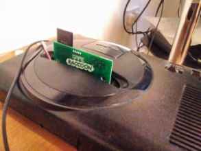
I've been in the shed

It was a lovely sunny day. I was sick of working on the computer, so it was time to get physical and do some stuff in my hated shed! I'm going to use these sanding bits I bought last year for my Xam'd mask. My plan is to work on a shell half at a time, clamping it in a sturdy vice, wrapping all points of contact in kitchen roll to spread the clamping force and prevent any scratches, and gently route away the edge of the shell until I have the slots I need. To reiterate, that's a large horizontal slot on the top, requiring me to remove a large section of the front piece and the upper right clip tongue from the back, and I need to neaten up the notch I've hacked away from the underside interior wall for the regulator capacitor. • Go slow! Brush away the dust frequently. • Clamp correctly. I was using an unsecured but heavy work vice, but even then sometimes the lateral force exerted on the clamped shell half during sanding was enough to make things rock and slide about. • Use the speeds of your tool correctly. Fast speeds are neater and quicker, but are often too quick. • Check for melted plastic often. As you grind away, you'll also be making a lot of heat, which will cause the flaked away fragments of case to soften and melt together and generate crusts of material in hard to reach areas if you work constantly for too long. I was going to do just one complete shell, but there's no reason for me to stop now that I've got the stuff out. If I need more shells, I'll buy them. After I'm done, they're going in a tub of red hot washing up liquid for a few hours and getting a serious rubbing down before they go anywhere near my Mega Drive or my electronics kit: they're going to be covered in dust and muck from the shed and vice and everything else that the outside world is made of. Also a shower is a good idea, you stinky thing. The large notch on the front piece isn't as neat as I'd like, but I was constrained and did my best. I'm not pleased about the small scuff on the interior of the plastic from when I switched to a long cylindrical bit and moved too far in while attempting to remove some melted shards on the inside. Removing the clip tongue took a long time but I'm glad I didn't try to hack it off with a knife first; I'm sure I would have shattered the piece. The notch on the interior wall was simple. I made it wider and deeper than it needed to be, since I wanted to smooth out the notch I hacked but only had a wide sanding ball in my kit. What's most important is that I haven't cracked either the front or the back, nor distorted it with heat and pressure so it doesn't fit together correctly any more. You shoulda seen the other guy! This first attempt was originally as neat as its brother, but I thought I could make the SD card slot more uniform by fastening the cart halves together and applying the sanding bit from above to make a rounded-rectangular hole. Good in theory, but not with my tools. Instead I now have an oversized, ugly, crooked slot hole with plenty of scuff marks. • If you might destroy it, buy two!!! After soaking, washing, rinsing, washing again because something fell in the bowl, rinsing again, drying and wafting about the place like a mad thing for an hour, I'm finally confident enough to assemble the cartridge with the board inside. Let's have a look how the slots have turned out. The SD card slot is functional, but not very impressive. A rub with something would be a good idea before I commit to this. The regulator capacitor arch is... well, I missed, hah. But it's big enough that the problem is solved anyway. This is the second board which I did after the messy one above, so I didn't have a hacked hole to work around, I just tried to imitate the messy board by eye. Always mark first then, I suppose! Let's put a card in. These are the first images of a completed Game Raccoon Revision 1! Yep, this is one of the working boards. I've removed the programming pins and auxiliary power supply, and it's ready to go! Ah... to tell you the truth, I'm a little disappointed. I was hoping that somehow the light of the LED would be caught by the transparent case and cause all the edges of the shell to light up sympathetically. As it is, it's just... transparent. Definitely not worth getting any tools out over though. I'm not sure whether or not I want to put a label on this now. Transparent works, but the pink isn't growing on me. It just looks weird. Distinct, but weird. Here's a helpful hint for putting these cart shells together: The shells I have were shipped without the screws installed: the screw pillars were completely clean and unused. There are four clips around the outside that hold the halves together very firmly, so you might choose to not even use the screws. To open the shells, hold the cart with the bottom facing you. Tuck your thumbs inside the bottom where the connector would be, and gently use a twisting/tearing style motion to try to unhook the lower side clip. Then you can move around the outside of the cart unfasting the rest. Before you attempt to screw the cart together, you can manually generate a thread on the front piece by screwing a screw into it while the halves are apart. It's a lot easier to do this now than to try it with the halves assembled. You'll need a lot of torque though: A pen-screwdriver like this pound shop gadget is awesome. Don't use cheapo jewellers screwdrivers like the one at the bottom there, it'll just grind itself and the screw head away and ruin everything. Pen-screwdriver every time. With the threads established, remove your screw, assemble the halves and you should be able to screw them together easily.

In the studio!

The world is still a wasteland of misery and pain, so let's pass the time by heading into the super secret Carr photography studio and take some Game Raccoon catalogue images! Gosh, it's pretty! :) The case sort of looks like jelly, don't you think? I think that next time I need to put some thought into making the PCB and the case co-ordinate with one another rather than just buying the cheapest one of each. Of course, you can't get shots like these without some high-quality lighting, a sturdy backdrop and a top of the range camera on a tripod. So, uh, here's the studio. Two pieces of A3 paper taped together with masking tape, propped up on a broken laptop since it's the right shape and has a solid hinge. I held the camera by hand - I use a Canon Powershot A800 since it's got a huge screen and takes SD cards and AA batteries rather than a proprietary lion. Here's the full gallery of Game Raccoon Revision 1 prototype photos, in case you'd like them, or if I need them. I have to say it's really crazy to see my logo and name on a completed cartridge like this. On the left is Arnold Palmer Tournament Golf, a standard Sega first-party cartridge. This is one of the first games on the system and has a simple board containing only the Sega-marked mask ROM. In the centre is NBA Live 95, an EA game in an elongated case with a yellow notch piece. The board contains additional save RAM and a battery. Notice how the board is longer, and also the mounting holes for the interior pillars are smaller and in a slightly lower position closer to the edges. The Game Raccoon board uses the GENESIS-LARGE component from Bruce Tomlin's part library. This part contains mounting holes for both Sega and EA-style cartridges. There's also a corresponding GENESIS-SMALL which imitates the small board on the far left. I thought a GENESIS-LARGE wouldn't fit inside a normal cartridge shell, but it fits inside the pink third-party case just fine. The MegaBoard was designed using... well, it doesn't match any of the components in the library. I think I used a generic connector component without any sizing lines (on the Dimension layer in EAGLE) and drew my own based around the measurements of the interior of an EA case. Here's a fact: the MegaBoard was laid out by EAGLE's autorouter because I'd never used the software before and didn't have a clue. I tried that with the Revision 0 board and it was a disaster, so I laid out all those traces and vias by hand one at a time! What happened to those sports games that were heading towards the executioner's axe? Safe and sound, dismantled, remantled, cleaned inside and out and tested. I haven't changed the battery on NBA but it looks like the saves are still intact! For sale if anybody wants them.

Issue One: There's no cute Game Raccoon!

There's one last major pending issue that I must address! There's no Game Raccoon in my Game Raccoon! It was always my intent to get assistance in designing and implementing a cute, simply-animated, low-colour cartoon raccoon to fill the time while regenerating the directory record cache and during installation, and now it's time. What I want is a nice, cute raccoon, somewhat like a Telegram sticker. A very 90s mascot. Or maybe 80s, no streetwise-ness, no edge, just cute. This is what I have so far. If you're interested in working with me on this, e-mail me!

Future wacky thoughts?

This is the part where I describe some of the silly things that ought to be possible with the Game Raccoon but I haven't programmed into either the 68000 or the PIC side yet. There's nothing I want to change about the hardware. It works, it's lovely. With very, very few exceptions, the ROM images I have that don't work on the Game Raccoon also fail in BlastEm for various reasons. Those images that don't fail in BlastEm are almost all Sonic hacks that rely on the presence of save RAM without testing that it's available first. The writing sequence from the SD card through the PIC to the Flash could be faster. I'm pretty sure that I've always had the MPLAB X project set to generating Debug images rather than Release images, which could be contributing untold numbers of millionths of seconds to the ultimate image writing speed. There's also some needless safety features present, such as ensuring the directionality of all the address and data GPIOs more often than is necessary. The Game Raccoon menu could be nicer, but there's not much more functionality that I could include on that side alone. To introduce major new features to the cartridge, new functions need to be added to the PIC firmware. At the start of this document, I wrote: • Allow 'Game Raccoon Enhanced' games - At present, the Game Raccoon PIC's intelligent functions are only enabled while the Boot partition is active. There's no link between the two, it just happens that when I switch from Boot to Game, I disable the PIC to prevent it intefering in the non-Game-Raccoon-aware running game image. If I could detect whether a game was 'Game Raccoon aware', then I could choose to keep the PIC active for these games and allow them access to the PIC's functions, and, through it, the SD card and the Flash module. This would allow games to save and load to SD card, or to load new segments of themselves into the Flash in real time for games of potentially limitless size. This is pointless because there are no such games, but I could write one! Having the !TIME register bidirectional would help a lot for this. Now that the !TIME register is bidirectional and definitely working, I can sketch some ideas about using it. Detecting 'Game Raccoon Enhanced' games would be trivial: immediately before launching the game, the full content of the installed game image is available to the RAM-resident menu for inspection. A special value somewhere in the header region could be specified and detected. Alternatively, the PIC itself could detect this condition when the GAME partition is bankswitched in prior to boot. From there, the PIC will be left in a state where it is still receptive to communication through the register rather than ignoring it. The same rules of communication between the Mega Drive and the PIC will apply: • The 68000 must be executing from RAM-resident code with all interrupts disabled. • Communication begins by writing a word value to the !TIME region. • The PIC engages isolation. The cartridge is isolated from the Mega Drive. During this time, the game ROM will be inaccessible. • The PIC performs some action based on the submitted word value. • The PIC writes a single word value into the register. • The PIC disengages isolation. • The game ROM becomes accessible again, this condition is detected by the RAM-resident 68000 code, and the RAM-resident code can read the value in !TIME and react to it. One word value is always traded for another, which is reminiscent of the message exchanges of SPI. To provide multi-byte communicaton, a protocol can be defined, where the 68000 master sends a message with either a known or unknown number of result messages, and must subsequently provide the appropriate number of communications towards the PIC slave to receive the full response. For example, if the 68000-side wanted to enumerate all the files in the current directory (assume that the PIC is holding state related to directory navigation), it could send a 'get number of files in current directory', to which the response would be a single word value. Then the next message could be 'get filename of item 0', to which the response would be of variable length. It could be sent as a zero-terminated string of bytes, one byte at a time, with the upper byte of the response word left blank. This upper byte could be used to return result codes, making the response word into a (status,result) pair of bytes. Alternatively, the first byte of the response could be the string length. These primitives could be used to construct a new menu system which obviates the directory record cache by allowing the 68000 to query the SD card 'directly' through the PIC. To complete this functionality, a 'boot the image with filename %S' command must be established, with the 68000 sending a variable length command to the PIC, with the string argument either null-terminated or length-prefixed. Another possibility is allowing the 68000 to read and write files itself on the SD card. Obviously, this is incredibly dangerous (don't store anything important on the SD card you're using for Game Raccooning anyway: that's just asking for trouble), so an abstraction in the vein of save game files could be used instead. Every game image on the card could have a number of binary save files associated with it: for game.bin there would be game.bin.sv0 up to sv9. Then the 68000 could send commands to the PIC to detect, create, read, write and delete these files. The API for this could look like this: • 'File F exists?' • 'Create new file F of length N' • 'Delete file F' • 'Open file F' • 'Close current file' • 'Read N bytes from offset O in current F' • 'Write N bytes to offset O in current F' The multi-byte commands would allow communication in blocks, though the full protocol must be followed for each word exchange. The speed of this system is yet to be determined!

August 2020 : Mega Drive 2

I wasn't sure whether I should add this as a new page on the Game Raccoon website, or add it to the Adventure 1 page. I think here makes most sense. I received a big box in the post this morning! It's a brand-old Mega Drive 2! A wise purchase! For me, not the seller - this thing is immaculate! It's time to party like it's 1993! I mentioned I didn't get all the fuss about video quality and RF cables earlier. The Mega Drive 2 (or is that Mega Drive II?) takes its own proprietary AV cables; the lead I have is for composite video with phono stereo audio. The picture is lovely and clear as you would expect, with the added benefit of my TV being offering a scaling mode that correctly fits the screen without altering the aspect ratio. It kind of is better than RF, but only slightly. And only because I'm running it on a HDTV from 2008. If you're playing on a CRT, unless you've got the indisputable pinnacle of televisions in absolutely perfect condition, what are you gonna see? I don't know much about Mega Drive 2s - this one doesn't look how I imagined it in my head. I thought it would be shinier, and it does look pretty shiny in that photo where it's on the dark table right after I gave it a bit of a clean. It's also really, really thin, like a pizza. It's has no pretensions about being anything other than a single square circuit board in a plastic box. When I was a kid, I always imagined it as a shiny black elite thing, like a futuristic spaceship. It's strange to me how over the years the Mega Drive 1 has become the familiar one and the 2 the unfamiliar one, even though the first time I saw a 1 was when my brother bought one a decade after the 16-bit era was over. The sound quality isn't as good as I expected either. The 'ring collect' jingle in the Sonic games sounds distorted, and some of the FM channels sound like they're hissing a little rather than being the super clear-as-a-bell, bell-like tones of the FM chip. If you've listened to Mega Drive or Adlib sound through headphones, you'll be very familiar with the perfect, artificial tones I'm describing. The bass is almost completely gone, and I don't know why. It might be to do with the AV cable and the stereo separation. I'm used to Mega Drives outputting mono sound from a TV through RF, like an Amiga using a modulator. When I fiddle with the sound settings on my TV, I can get the bass back if I tell the TV to ignore one of channels. I think I ought to look up online to see if there's anybody else who's noticed these things about Mega Drive 2s.

Who wore it better?

These Aliexpress pink shells are a very tight fit into the Mega Drive 2's cartridge slot, I must warn you. I can't recommend frequent insertion and removal at all. I have to use both hands on the cartridge and very deliberately use a lot of force easing the cart into the slot. It's only the collar of the slot itself that seems tight - there's only the thin upper shell of the case there, not a fully lined solid slot like you'd find on a Game Boy for example. At least I can be sure it's secure in there. Who wore it better do you think? The II is a bit of an ugly beastie I think. It's very easy to take awful shots of it. But I've got nothing to do while I'm installing Overdrive once more! Now that I have a Mega Drive 2 to test with, the last barrier has been eliminated. If this works, it means the Game Raccoon Revision 1 is capable of responding under the most extreme of circumstances and is ready for duty. If not, then I blew it designing the board and I'll have to take a few steps back and figure out what I did incorrectly. Would you like to see what happened?

Running Overdrive 1 on a Mega Drive 2 at long last, what happened?

Outstanding magnificent success! Every effect is present and correct, and the system runs from the very start with Eggman right through to the honky horn and the achievement notice. Speaking of which: I earned this. I'm going to print it out as a sticker and put it on my laptop, because boy was that a lotta fuss. But, as they say in Super Gem'Z, we made it! It's done! Everything can go back to normal now! That's how it works, right? Jumanji rules? No? Darn. Here's the effect that was giving me all that trouble. TITAN 512C FOREVER, the centrepiece of the demo. In Revision 0, you could see the rainbow colours of the previous effect (the robot sliding left and right across a rainbow horizontal striped background) in the border only, and then the borders go black and the text character sprites from 512C begin to orbit the sphere as solid white squares before the VDP crashes. In Revision 1 on the Mega Drive 1, the effect works for several frames before the VDP gives up and shows the full contents of the screen in the palette at that moment in time. In Revision 1 on the Mega Drive 2, the full effect plays from start to finish, with the graphic descending into view, the letters moving across the surface while the text colour cycles, then everything fades out.

So what else does the Mega Drive 2 run that the Mega Drive 1 doesn't?

That's a good question! * hours of trying demoscene productions and Sonic mods later* There's been no improvement on the Sonic mod front, I'm afraid. I think they're as compatible as they're ever going to be. Sonic mods are just gonna be Sonic mods. Actually, no, there was one mod that showed a noticeable improvement: the very clever boss rush hack Robotnik's Revenge now lets me play as Sonic as well as Tails without crashing half way during a boss transition. 16:02.11 as Sonic. :) That last boss takes for-freakin'-ever. Sonic Sad Hill Hell of Green Hill Zones still crashes too quickly to let you through the full main story, and Metal Sonic Rebooted still reboots. Both revisions of Sonic 1 With Fries let me begin the game, but they inevitably crash at the end of an Act. It has a strange reimplementation of Super Sonic without his new sprites, and sometimes he'll begin to transform but forget his lines and be trapped suspended there forever puching the air with a goofy smile on his face. I was really looking forward to messing about with strange unlicensed games like Squirrel King and Pocket Monsters 1 and 2, but they all fail in various ways, crashing or just malfunctioning. They just mustn't be compatible with a PAL system. It's back to the demoscene! Day Trip by Planet Earth. On the Mega Drive 1 I can only get three notes of the bassline before this demo crashes. On the Mega Drive 2, everything is wonderful and I can receieve my well-needed prescription for additional cubes. Smell Those Douglas Firs by Limp Ninja. I don't know why this demo wastes your time with still images of the effects it's about to show, but it's well known that I don't understand showmanship. The tunnels, vortices and bump mapping are all (seemingly) done in real time, it's quite something to see it happening on a real Sega system, and a great way to end my Revision 1 Adventure. Verdict: the Mega Drive 1 is in desperate need of recapping! I think perhaps the aging capacitors are causing certain chips' responses to signals to be slowed to the point where they're missing their required windows, causing invalid values to be read, and everything to blow up. Check your old systems for bad capacitors! Batteries are especially bad, you do not want a Varta battery leaking and dissolving your board. If you have any old system with any kind of non-volatile RAM in it, take a look before it's too late.

The end!

Thank you for reading this adventure! Your eyes must be awfully tired. I recommend you take a break and go out for a walk! Keep an eye on the Game Raccoon website for updates! If you'd like to read about the Game Raccoon Revision 1 as a finished device, go to the Game Raccoon Revision 1 Technical Report. Back to the Game Raccoon front page